Verify Accelerometer Power and Constant Current Supply
December 21, 2018
Definitions and Reasons
Automated Calibration Verification
Verify Accelerometer Power and Constant Current Supply
Back to: Preserving VR Hardware Accuracy
Before running an automated verification, we recommend measuring IEPE voltage and current to ensure the accuracy of the hardware. To do so, the following equipment is required:
- (3) 50-ohm terminators
- Dual banana to BNC adapter
- 36″ BNC cable
Instructions
- Open VibrationVIEW and connect the workstation PC to the VR9500.
Check IEPE Voltage
- Turn on the accelerometer power for Channels 1 to 4.
- Connect three 50-ohm terminators to Channels 2, 3, and 4 (Figure 3.1).
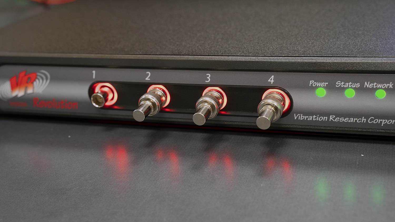
Figure 3.1. 50-ohm terminators connected to Channels 2 to 4.
- Insert the banana adapter into the two holes on the top right of the DMM’s front panel. They should be labeled as Input – HI and LO. Make sure the ground pin is connected to the LO port.
- Connect one end of the BNC cable to the banana adapter (see Figure 3.2.)
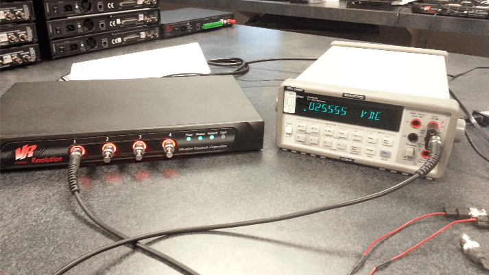
Figure 3.2. Connecting the VR9500 to the DMM to read voltage.
- Press the top left button marked V DC.
- Connect Ch 1 to the DMM.
- Measure and record voltage (24 Volts DC ± 2.4 Volts = 21.6Vdc – 26.4Vdc tolerance). Any channel not being measured should have a 50-ohm terminator installed to prevent any leakage across channels.
- Repeat this measurement on each of the remaining inputs. Any channel not being measured should have a 50-ohm terminator installed.
Check IEPE Current
- Turn on the accelerometer power for Channels 1 to 4.
- Connect three 50-ohm terminators to Channels 2, 3, and 4 (Figure 3.1).
- Set up the DMM to read DC amperage by pressing the button labeled D CI in blue.
- Press the Shift button on the lower right, and then press the DC V button on the upper left.
- Rotate the banana adapter down 180 degrees so it is connected in the bottom two right holes on the DMM’s front panel. The ground pin should be connected to the LO port (Figure 3.3).
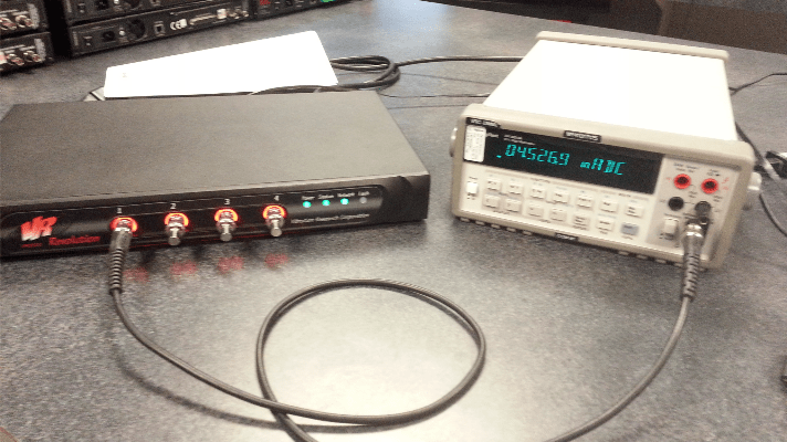
Figure 3.3. Connecting the VR9500 to the DMM to read the current.
- Connect Ch 1 to the DMM.
- Measure and record amperage (4.66mA ± 0.77mA = 3.89mA – 5.43mA tolerance). Any channel not being measured should have a 50-ohm terminator to prevent any leakage across channels.
- Repeat this measurement on each of the remaining inputs. Any channel not being measured should have a 50-ohm terminator installed.
| Ch1 | Vdc: V | Tol: 24V ± 2.4V (21.6V – 26.4V) |
| Idc: mA | Tol: 4.66mA ± 0.77mA (3.89mA to 5.43mA) | |
| Ch2 | Vdc: V | Tol: 24V ± 2.4V (21.6V – 26.4V) |
| Idc: mA | Tol: 4.66mA ± 0.77mA (3.89mA to 5.43mA) | |
| Ch3 | Vdc: V | Tol: 24V ± 2.4V (21.6V – 26.4V) |
| Idc: mA | Tol: 4.66mA ± 0.77mA (3.89mA to 5.43mA) | |
| Ch4 | Vdc: V | Tol: 24V ± 2.4V (21.6V – 26.4V) |
| Idc: mA | Tol: 4.66mA ± 0.77mA (3.89mA to 5.43mA) |