Setup Monitoring & Control for a Testing System
December 28, 2018
Back to: Preventative Maintenance
Personnel safety is the most critical factor in a testing lab. The next is protecting the investment in testing equipment. These two issues coincide, as steps that mitigate risks to equipment also promote safety.
One effective way to mitigate equipment risk is to remotely monitor and control a shaker and amplifier using control software. Automated system monitoring allows lab personnel to review changes over time and helps them predict when preventative or reactive maintenance is needed. It also lets lab managers establish start-up and shut-down procedures that protect the equipment and technicians.
Monitoring System Variables
Transducers can monitor voltage, current, and temperature to track the condition of the shaker and amplifier. Monitoring these key variables will give technicians and managers the ability to:
- Determine if the system is functioning properly
- Create limits on each variable to ensure that the system is not overtaxed beyond any safe operating range
- Track the changes that inevitably occur over time due to wear and tear on system components
Voltage Monitoring

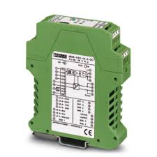
Figure 1. Voltage monitoring transducer from Phoenix Contact.
A voltage monitoring transducer can scale armature and field voltages. Engineers can then wire the scaled voltage to an analog remote input on the vibration controller to view the field and armature voltage while running their tests. Knowing these values helps avoid overtaxing the shaker system for an extended period and provides a better view of a particular test’s power requirements.
A test’s power requirement increases as the shaker and amplifier performance degrades over time. The engineer should shut down the system for maintenance if the voltage exceeds a predetermined threshold value during a simple diagnostics test. This maintenance can range from a simple cleaning to replacing the armature coils or amplifier power modules.
Current monitoring

Figure 2. Current monitoring transducer from Phoenix Contact.
Many current monitoring transducers are available, but the Hall effect transducer is the easiest to install. This transducer is an inductor clamped around a power wire that converts the induced voltage into a relative current flow and outputs a scaled current measurement in millivolts per amp.
The current required to run a test will increase over time as the shaker performance degrades. Consistently monitoring the field and armature current will provide the engineer with a trend of information that they can use for diagnosing system problems.
Temperature Monitoring
A thermal couple mounted to a shaker head has two uses. First, it can monitor the effectiveness of the active cooling system. If the temperature increases significantly during a standard test, the filtering system may need to be cleaned.
Second, knowing the temperature can mitigate equipment risk. When running a test at or near the system limits, the increased power requirements cause the shaker to operate at a higher temperature. By tracking this temperature, the engineer can safely operate the system without risking the integrity of the system’s interior components. Most shakers have a temperature limit switch integrated into the interlock, but knowing the temperature and tracking the temperature change is key to troubleshooting and maintenance procedures.
Establishing a Baseline
Engineers must establish a data baseline for voltage, current, and temperature data to track changes in system performance. They should acquire and document the baseline data when installing a new system. This data act as a starting point for all documentation throughout the lifetime of the amplifier and shaker.
Semi-annual or annual preventative maintenance will extend the life of the equipment investment, but developing documentation to predict downtime increases the effectiveness of the entire testing lab. Engineers can proactively order and organize parts, equipment, and labor, reducing overall downtime and avoiding the stress of emergency shutdowns.
Programming Automated Start-up and Shut-down
Adding relays connected to the remote outputs allows a lab to program a shaker system startup and shutdown sequence. This sequence ensures that actions occur in the correct order and allows for an appropriate cool-down time before powering off or moving to standby mode.
Engineers can configure the startup and shutdown sequence to turn on the armature and blower and then wait for the start of a test to turn on the field supply. After the test, they can set the field to turn off, leaving the blower to run for a set period before the rest of the system turns off. This configuration ensures that the shaker has adequate time to cool, even if the test reaches completion in the middle of the night when no one is available to shut down the system.
