How to Calibrate Piezoelectric Accelerometers in VibrationVIEW
January 2, 2019
Calibrating Accelerometers
Back to: Calibrating a Piezoelectric Accelerometer in VibrationVIEW
Equipment
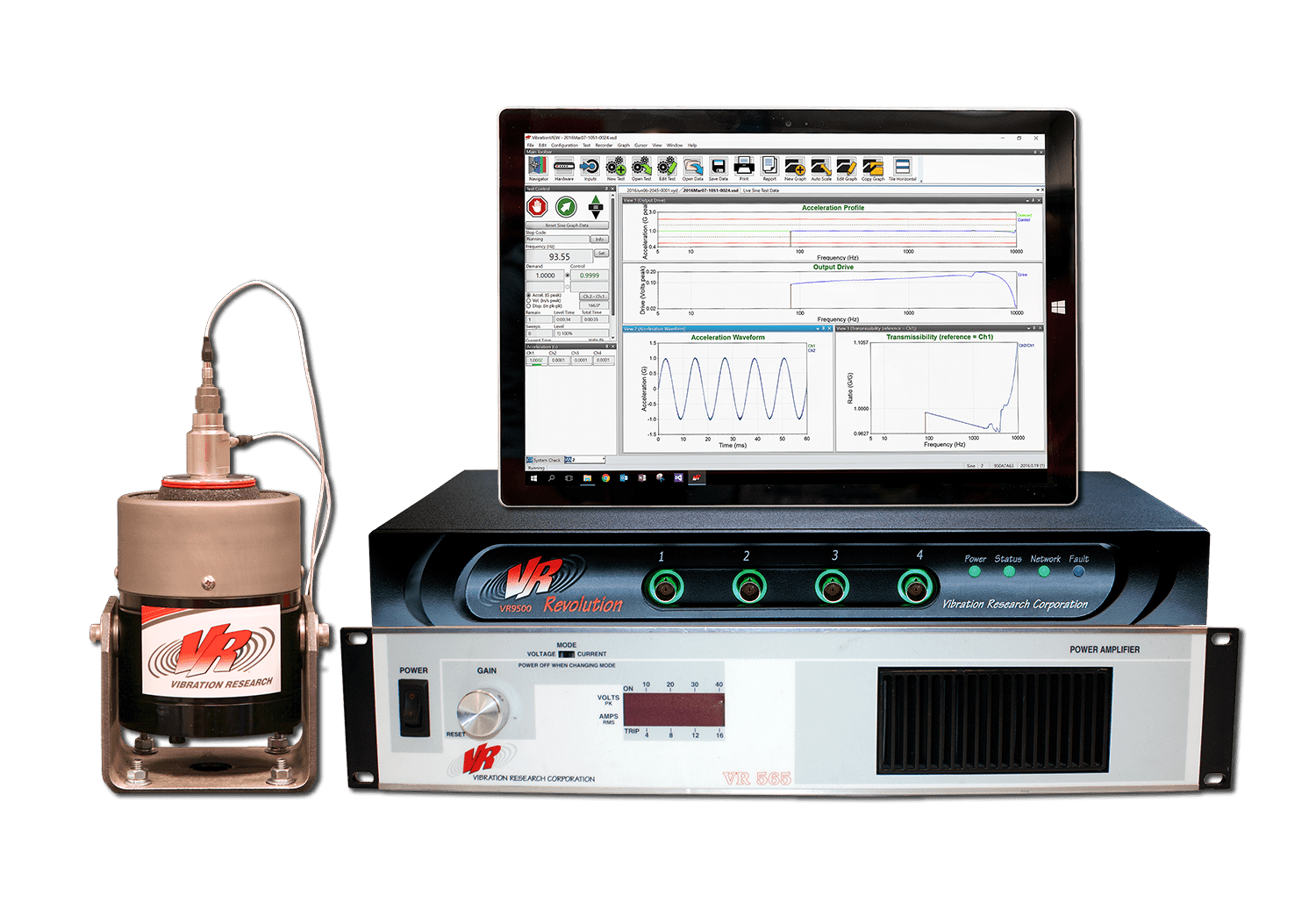
- VR9500, VR9700, or VR10500 vibration controller
- Windows PC with VibrationVIEW Sine software and Accelerometer Calibration add-on package
- VR5200HF shaker and amplifier
- Reference device (REF), such as Dytran 3027B back-to-back accelerometer
- Piezoelectric accelerometer
- Cables for shaker system setup
Setup
- Connect and power the PC, controller, shaker, and amplifier
- Mount the accelerometer to the REF in a back-to-back configuration
- Stud mount the REF to the shaker head
- Stud mount the accelerometer to the top of the REF
Make sure to use a proper mounting technique (see Accelerometer Mounting Tip Sheet).
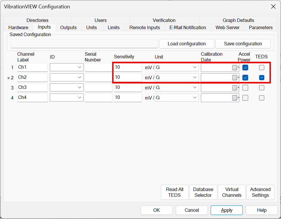
- Configure the inputs
- Connect the REF to Ch1; connect the accelerometer to Ch2
- Select Configuration > Inputs
- Enter the sensitivities for Ch1 and Ch2
- Turn on accelerometer power for Ch1 and Ch2
- If the accelerometer supports TEDS, select the TEDS checkbox for Ch2
- Configure the system limits
- Navigate to the Limits tab
- In the Shaker Model drop-down lists, select Vibration Research, VR-5200
- Select OK
- Create the calibration test profile
-
- Select the Navigator button; the dialog will appear
- Select the Sine (more) folder > Sine Accelerometer Calibration > Create
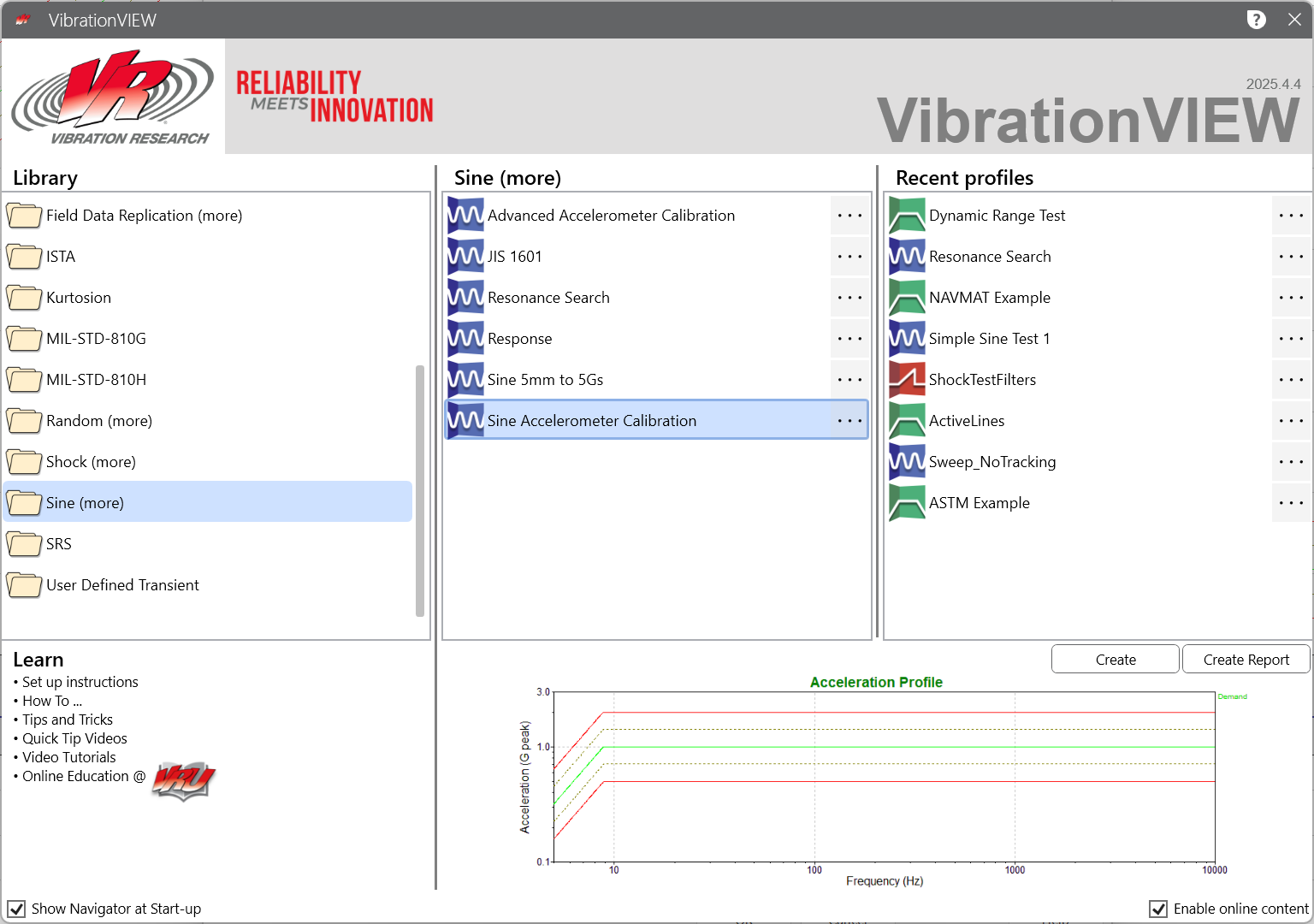
- The Sine Test Settings dialog will appear
-
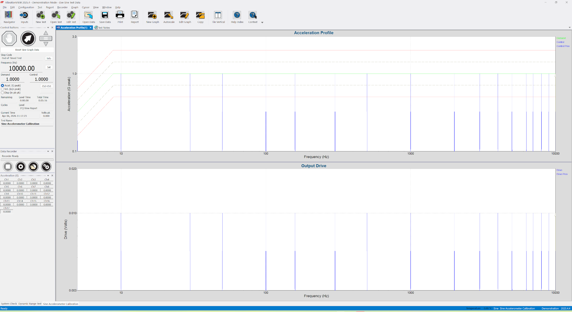
The default test profile consists of a series of sine dwells from 5 Hz to 10,000 Hz. The calibration value is calculated from the dwell at 100 Hz. This dwell is the first and longest of the test, with a duration of 15 seconds.
External facilities typically calculate accelerometer sensitivities at 100 Hz. The test profile can be adjusted if a different frequency is preferred.
Next is a series of 5-second sine dwells from 5 Hz to 10,000 Hz. These frequencies are customizable; any combination can be added or removed from the list.
-
- After any adjustments, select OK
- Save the test profile
- Run the test
- Select the Run button

-
- Complete the HTML form
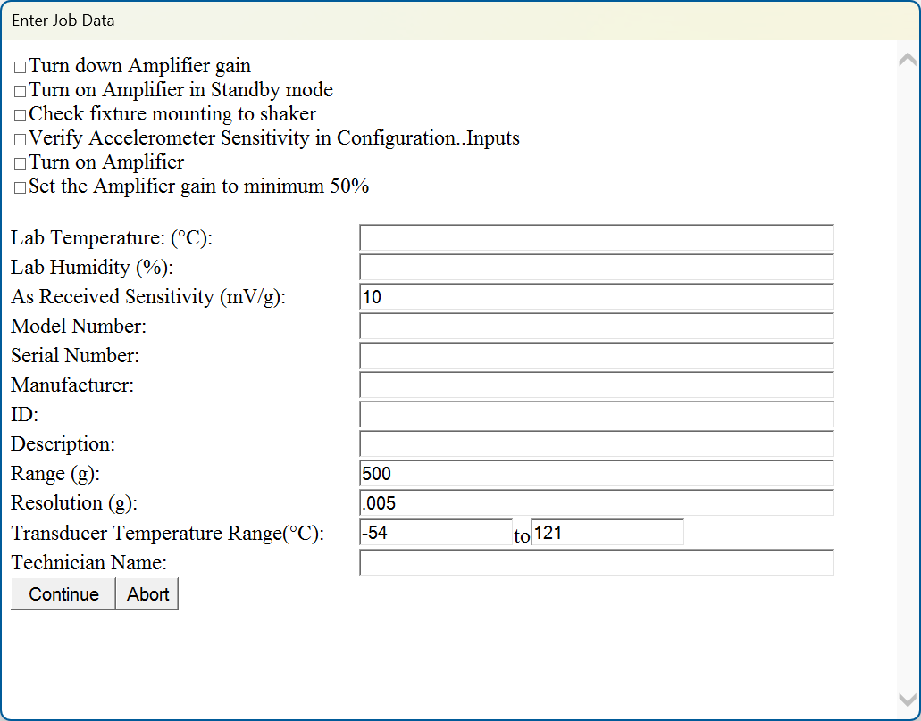
-
- Select Continue
The calibration will run at 100 Hz. After the calibration is complete, the test will verify the accuracy across a full operating range of frequencies.
- Save the test data
- A Save New Values dialog will appear
- Select Save New Values and VibrationVIEW will update the TEDS information stored on the accelerometer
- VibrationVIEW will generate an Accelerometer Calibration report as an Excel file
The results from the calibration procedure are displayed numerically and graphically in the report. The response of an accelerometer is not perfectly linear, so responses and tolerances will vary depending on frequency. The standard template (which is customizable) displays the phase and amplitude response of the newly calibrated accelerometer, along with a chart showing each frequency dwell and the deviation at that frequency.