Introduction to Analyzer Graphs
January 2, 2019
Getting Started with Analyzer
Primary Graphing Functions
Back to: VibrationVIEW Analyzer Software Package
The VibrationVIEW Analyzer package displays data in four primary graphing functions and two less common ones.
Analyzer Graphing Functions
Transfer Function
The transfer function graph displays the ratio of cross-spectra values for two signals at a specific frequency range and the phase relationship between the signals. It is relevant to random and shock testing.
Total Harmonic Distortion (THD)
THD determines a signal’s harmonic content by comparing its acceleration at a specific frequency to the accelerations at the next ten harmonics of that frequency. THD can also measure how well a shaker recreates a signal from a vibration controller. It applies to sine testing.
Coherence
A coherence graph is a plot of a correlation calculation value in the frequency domain. It is a statistic that examines the relationship between two values or signals. Two signals are coherent if they have a constant phase difference and the same frequency and waveform. Coherence graphs are most often prevalent in random and shock testing.
Cross Spectrum
A cross-spectrum graph displays the amplitude and phase of multiple signals for a set frequency range. It applies to random testing.
Spectrum Graph
A spectrum graph is the plot of a signal’s fast Fourier transform (FFT). The scatter plot compares one selected input to a second one.
Additional Options in Test Settings
When the Analyzer key is enabled, two additional tabs appear in the Test Settings dialog: Pre-Test and Analyzer (Figure 1.1).
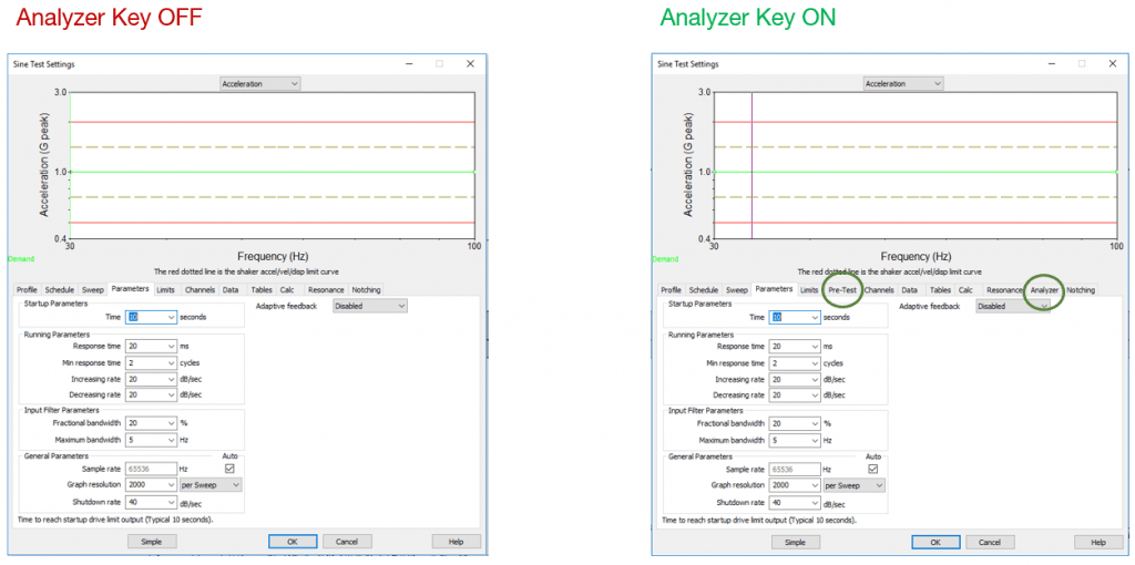
Figure 1.1. Test setting options specific to the Analyzer key.
Pre-Test Tab
Under the Pre-Test tab, select the Enable Pre-Test option to perform an open-loop pre-test analysis and a prediction of test results. The pre-test sends a low-level, open-loop output to a shaker with just enough amplitude to overcome the shaker’s noise floor.
The pre-test option uses the output and measured response to predict the amplitude levels of the full-level test and provide insight into test responses, such as the location of resonances. Early visibility is particularly helpful when there is a concern about potential over-testing.
To use the Pre-Test option, select New Test, and select the appropriate test type. Then, select Advanced > Pre-Test. Select Enable Pre-Test to configure the pre-test (Figure 1.2). The configuration includes the target frequency range, outputs, and channel limits.
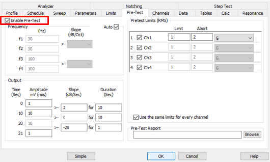
Figure 1.2. Pre-test configuration.
Analyzer Tab
Navigate to the Analyzer tab to set the analysis parameters. The parameter choices will depend on the test type (Figure 1.3).
Note: For sine tests, it is very important to select the Swept THD option before starting the test so that the software collects THD data. Additionally, it may be beneficial to increase FFT Analysis Lines beyond the default value of 2,048.
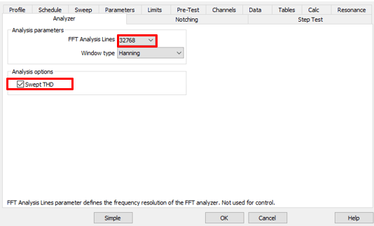
Figure 1.3. Analyzer tab parameters for a sine test.
Programming the Analyzer Key
VibrationVIEW Analyzer is an optional feature, and the software key must be programmed to enable the feature. Please contact sales to purchase or renew an Analyzer key.