Create Differential Cables
December 20, 2018
Definitions and Reasons
Automated Calibration Verification
Verify Accelerometer Power and Constant Current Supply
Back to: Preserving VR Hardware Accuracy
It may be necessary to create differential cables when performing an automated VR9500 calibration verification. The directions are as follows:
Equipment
- (1) Pomona 4969 BNC
- (2) Pomona 4970 BNC
- (1) small-diameter heat shrink
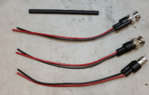
Figure 2.9. Required parts.
Assembly Instructions
- Remove the black leads from both Pomona 4970 parts.
- Cut the heat shrink in half.
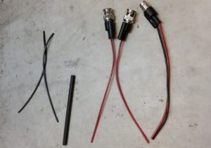
Figure 2.10. Remove black leads and cut heat shrink.
- Strip the ends of all the wires.
- Place the heat shrink on both leads of the Pomona 4969.
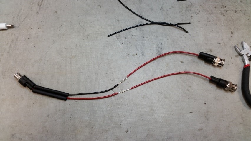
Figure 2.11. Prepare parts.
- Solder one Pomona 4970 (red lead) to each lead of the Pomona 4969.
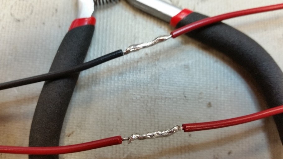
Figure 2.12. Solder leads.
- Move the heat shrinks over the soldered connections.
- Use a heat gun to melt the heat shrinks into place.
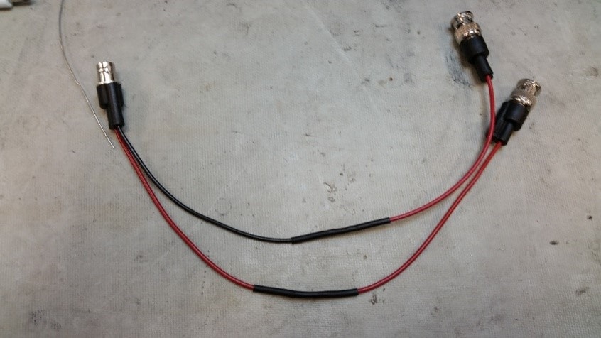
Figure 2.13. Apply heat shrinks.
- Label the red-red lead as DRIVE.
- Label the black-red lead as COLA.