Types of Shock Testing Machines
March 20, 2020
Back to: Shock Testing
As discussed in a previous lesson, the type of machine an engineer selects to generate a classical shock pulse depends on the mass of the device under test (DUT) and the desired pulse amplitude, duration, and shape.
For a more in-depth understanding of shock testing, let’s review several types of shock testing machines.
Mechanical Shock Machines
“Mechanical shock machine” is a generic title for a system without a closed-loop controller that excites the table to which the DUT is mounted. Mechanical shock machines include mechanical systems designed to excite a DUT with a transient pulse of a defined shape.
Examples
- Drop-shock machines
- Lightweight shock machines
- Medium-weight shock machines
- Hopkinson bar
The pulse shape, duration, and amplitude of a mechanical shock machine can be changed by adjusting the speed of the machine’s movement or the impact of its movement on the DUT.
Larger Mechanical Shock Machines
The United States Navy first developed lightweight and medium-weight shock testing machines. These machines drive a pendulum hammer into the stationary table to which a DUT is mounted. MIL-S-901D defines the requirements for “shipboard machinery, equipment, systems and structures,” including the requirements for test machines.
Test engineers use a floating shock platform for oversized DUTs. The platform necessitates a barge floating in a quarry or lake and explosive charges to generate different shock levels.
Below are two composites of MIL-S-901D standard shock testing machines for lightweight and medium-weight equipment.
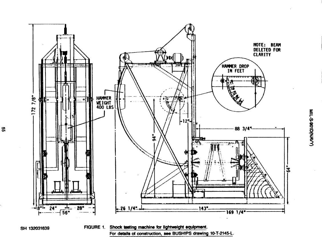
Shock testing machine for lightweight equipment from MIL-S-901D.
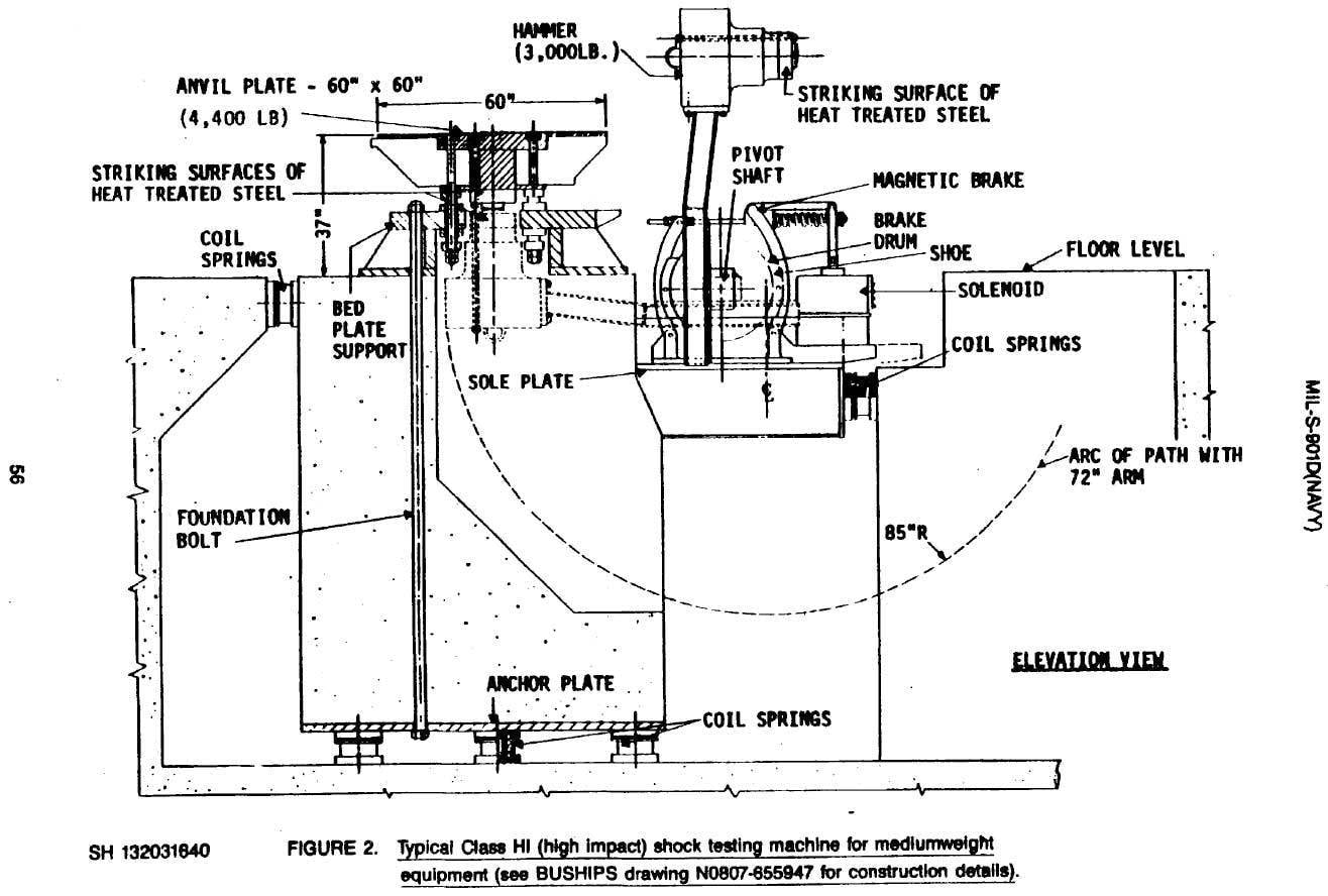
Shock testing machine for medium-weight equipment from MIL-S-901D.
Drop Shock Machines
Drop shock machines can generate many of the classical shock pulses. A drop shock machine drops a table onto a seismic mass and uses different programmers to change the shape of the generated pulse.
Drop shock machines use the rapid deceleration of a DUT to generate the classical shock pulse defined by the test specification. A drop shock machine consists of a table mounted to two parallel columns. The machine raises the table to a pre-calculated height and then drops it to the “ground.” In this context, the ground is a reaction mass that absorbs some of the shock to prevent unwanted contact with the actual ground.
Free-fall Drop Shock Test
For a free-fall drop shock test, the DUT is mounted to the table of a drop shock machine. The acceleration and the shape of the shock pulse is determined by two factors: the height from which the DUT is dropped, and the material on the impact surface. The height determines the overall peak acceleration. The higher the height, the greater the acceleration when the DUT strikes the reaction mass.
When a machine is not tall enough to generate the desired amount of acceleration through the force of gravity, elastic bands or pneumatic cylinders can be added to increase the velocity of impact with the programmer. The programmer is situated on the reaction mass at the location where the falling table impacts. The dynamic response of the programmer determines the pulse shape.
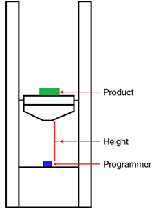
Figure 1.6. Diagram of a free-fall drop shock machine.
Half-Sine Pulse
Half-sine is one of the more common classical pulse shapes. A half-sine shock pulse can be replicated on a drop shock machine by placing rubber material or another elastomer on the surface of impact. The machine raises the table to the height necessary to achieve the acceleration for the half-sine pulse. Then, it releases the table; the table strikes the rubber surface and rebounds.
To see the pulse shape generated by a half-sine drop on an acceleration waveform graph, we need to consider the change in the DUT’s velocity from the time the table strikes the impact surface.
Example
Creating a Half-Sine Pulse with a Spring Programmer
To further illustrate a half-sine pulse, let’s consider the following:
A spring is placed on the reaction mass instead of a dense rubber pad. The DUT has a high velocity just before contact with the spring. When the table contacts and subsequently compresses the spring, the DUT’s velocity decreases.
At first, the velocity decreases slowly. The acceleration is relatively low, and acceleration is a change in velocity. However, as the spring becomes more resistant to compression, the DUT’s velocity decreases quicker because the change in acceleration is greater.
Eventually, the compression of the spring reaches its limit, and the acceleration is at its greatest point. Brought to a standstill, the DUT begins moving in the opposite direction. The tightly compressed spring creates a high change in velocity because the change in acceleration is high.
As the DUT continues moving upward and the spring becomes less compressed, the force pushing the table decreases in correspondence to the decreasing acceleration. An idealized graph of a half-sine shock pulse is shown in Figure 1.7.
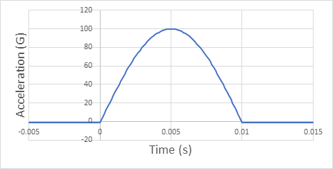
Figure 1.7. Creating a half-sine pulse with a spring programmer.
The DUT’s acceleration was -1G just before impact because the only acceleration was due to gravity. When the table struck the spring, and the spring compressed, the acceleration increased to 100G. When the table rebounded off the spring, the acceleration decreased. Eventually, there was only negative acceleration (downward) due to gravity.
Programmers and Pulse Width
A spring was used for the thought experiment above, but similar principles apply when the material on the impact surface is rubber or another elastomer. Similar to a spring, rubber compresses and then decompresses.
In “A Minimal-Mathematics Introduction to the Fundamentals of Random Vibration & Shock Testing,” Wayne Tustin writes,
“During the first half of the half-sine pulse, the carriage is entering the rubber. During the second half of the pulse, the carriage is exiting the rubber” (pg. 360).
The durometer, a tool used to measure the hardness of the programmer, determines pulse width (the time duration of the pulse). The softer the rubber, the greater the pulse width. Similarly, the more the rubber compresses, the greater the resistance to compression there will be. At the peak compression point, the DUT rebounds and the rubber decompresses (Figure 1.8).
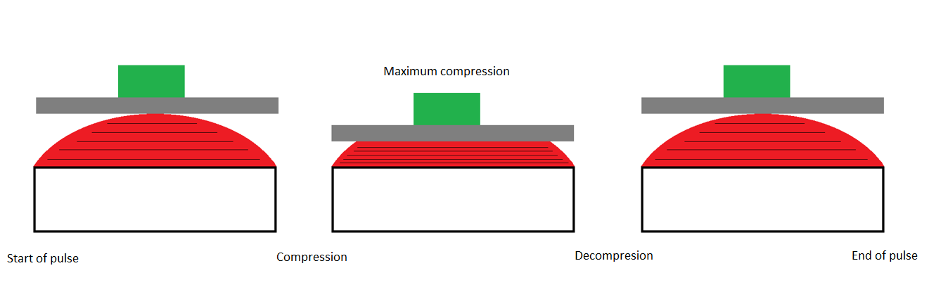
Figure 1.8. Maximum compression of a rubber programmer.
Terminal-Peak Sawtooth Pulse
Terminal-peak sawtooth is another common classical pulse. It can be generated using lead castings designed for this purpose.
When the table falls, the only acceleration is generated by gravity (-1G). When the table hits the lead castings, the DUT experiences acceleration in a positive direction (force equals acceleration times mass.) The force increases at a near-constant rate because lead is easier to compress upon impact.
Eventually, the lead cannot compress further and the DUT stops moving. At this point, the acceleration drops to 0 nearly instantly. Below is an idealized graph of a terminal-peak shock pulse with a maximum acceleration of 100G and a 10mS duration (Figure 1.9).
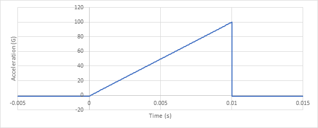
Figure 1.9. Idealized graph of a terminal peak shock pulse with a maximum acceleration of 100G and a 10mS.
It is important to note the difference between acceleration and velocity in this context. In the most recent example, the acceleration increased throughout the duration of the pulse, but the velocity decreased rapidly. Just before contact with the lead castings, the table was moving quickly. Over the course of 10mS, the velocity dropped to 0.
If we were to view the drop at regular speed, we would not notice the compression of the pointed lead castings because the motion would occur so quickly. However, in that time frame, the lead points compress, and a greater force (corresponding to a greater acceleration) is applied to the table in the opposite direction until the motion stops.
The pulse amplitude for classical shock pulses on a drop-shock table can be adjusted by changing the distance from the table to the programmer. In some cases, springs or rubber bands are connected from the seismic mass to the table to create a velocity other than gravity.
Pneumatic Shock Machines
Pneumatic shock testing machines use compressed air to drive a table into an impact surface. The impact surface uses different programmers to create different classical shock pulse shapes.
Similar to a free-fall shock machine, rubber pads or elastomers can be used with a pneumatic shock machine to generate a half-sine pulse. Lead pellets can create terminal-peak pulses, and pneumatic cylinders can create trapezoidal pulses.
Pneumatic cylinders generate an impulse force rather than relying on gravity, making it possible to generate much higher acceleration values in a shorter vertical distance.
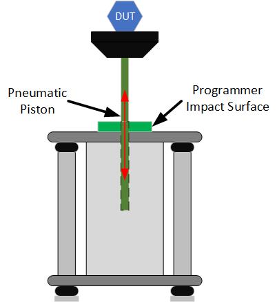
Figure 1.10. Diagram of a pneumatic shock machine.
Conclusion
Several factors determine the type of machine an engineer selects to generate classical shock pulses. One of the more common mechanical machines is a free-fall drop shock machine. With drop shock machines, the programmer can be changed to achieve the desired pulse shape.
In the next lesson, we’ll learn about another device for generating a shock test: shakers.