Classical Shock Tests on Shakers
April 13, 2020
Back to: Shock Testing
There are many considerations when selecting the appropriate shock-generating device for a test. A shaker can reliably generate many pulse shapes. For a routine shock test, it can be a cost- and time-efficient option.
However, there are a few caveats to consider when running a shock pulse on a shaker. When a shock machine generates classical shock pulses, a large seismic mass, brakes, gas pistons, or some other mechanical method arrests the table. Vibration shakers do not have mechanical stops for this purpose.
Additionally, shakers can only generate a fixed amount of velocity and displacement. To address this limitation, the shaker controller employs a process called compensation.
Compensation Pulses in Classical Shock Tests
Classical shock pulses are unipolar acceleration pulses. The goal of running a classical shock pulse on an electrodynamic shaker is to generate the same, or a similar, change in velocity as a shock machine. Classical shock pulses are intended to replicate the effect of a shock machine, where the primary characteristic for evaluation is the change in velocity (delta velocity).
To run a classical shock test on a shaker, the pulse must start and end at zero acceleration, velocity, and displacement. The test engineer must add pre/post-compensation pulses to drive the shaker back to these zero parameters.
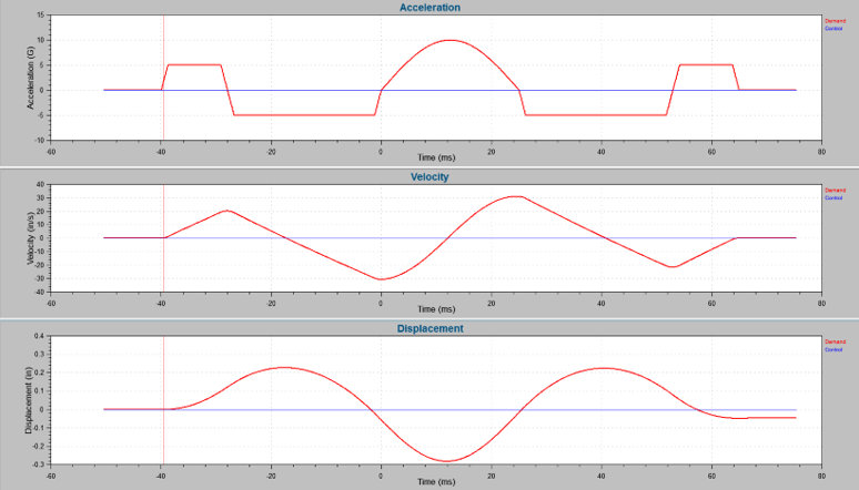
Classical shock pulses with pre and post-pulse compensation.
Without the compensation pulses, the generated signal will not stop velocity and displacement. Continued velocity and displacement can be dangerous and damaging.
Benefits of a Shaker System
Adding compensation pulses changes the pulse’s frequency content; however, there are many benefits to running classical shock pulses on a shaker system.
For the most part, the pulse can be run in a positive and negative direction without re-orienting the product. Therefore, the product only needs to be re-oriented three times to excite all six orthogonal axes per the requirements of most shock standards. Additionally, the pulse is repeatable, which makes analysis and comparison easier and reduces measurement uncertainty due to human variables.
Requirements for Compensation Pulses
In the paper, “Shock’n on Shakers,” published in the Sound and Vibration Magazine, George Fox Lang details the requirements for compensation pulses in classical shock tests.
Most importantly, compensation must be applied when running a unipolar pulse on a shaker. Compensation pulses can be added before or after the test pulse and, generally, should include two pulses of opposite sign.
The amplitude of the pulses can be lower than the standard definition, and they do not need to be equal. However, the lower the amplitude of the compensation pulses, the longer the total duration of the standard pulse. This caveat can pose a controller problem.
Additionally, the compensation pulses do not have to be the same shape as the standard.
Analogy: Importance of Compensation Pulses
The following analogy helps explain why shaker shock tests require compensation pulses.
Imagine a car stopped at a stop sign. In its current state, the car has zero acceleration, velocity, and displacement. When it accelerates, the velocity and displacement, or total distance from the starting point, increases.
After putting the pedal to the floor—thereby reaching max acceleration—the driver slowly takes their foot off the pedal. Assuming there is no negative acceleration brought on by friction, wind resistance, etc., the car has now reached zero acceleration. Although the driver has stopped accelerating, the car is still moving at a constant velocity, and its displacement is increasing. This analogy reminds us that zero acceleration does not necessarily mean zero velocity and displacement.
Without compensation pulses, a similar situation would apply to the shaker’s armature. When the acceleration returns to zero, the velocity and displacement will continue to increase until the motion of the shaker is arrested. The shaker’s mechanical stops are not designed for this action. It would introduce significant additional shock into the product, most likely causing significant damage to the shaker.
Holes in the Half-Sine Frequency Spectrum
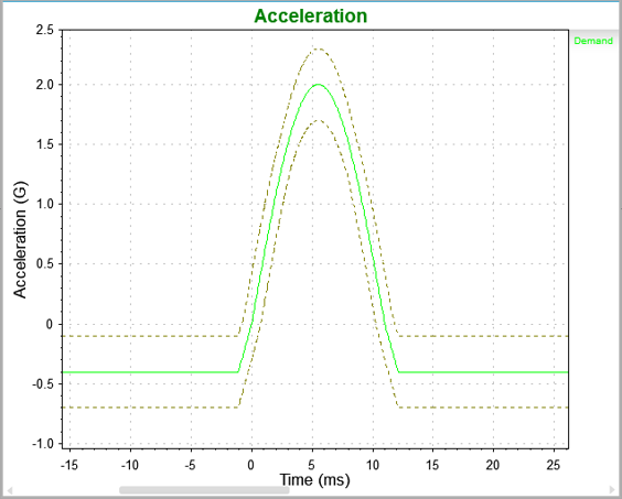
Half-sine pulse.
The half-sine pulse is primarily used to excite mechanical resonances. However, half-sine pulses introduce large holes in the frequency spectrum.
These holes are less defined if the test is run on a shaker because of the compensation pulses’ effect on the overall frequency response. However, the holes are still visible. If a product’s resonance lines up with one of them, very little acceleration would be driven into the resonance, and there would be minimal excitation.
If we remove the pre and post-compensation pulses and reanalyze the time waveforms, the “holes” in the frequency spectrum become more defined.
These holes can be shifted to higher/lower frequencies by changing the pulse duration. The location of these holes must be considered when running a half-sine pulse. If the DUT’s resonant frequency falls within the bandwidth of these holes, the frequency will not be excited. In such cases, the test will be ineffective, and the product will be improperly tested.
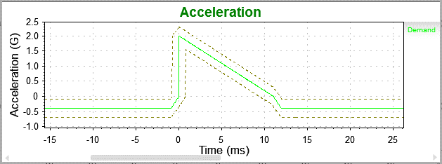
Terminal peak (sawtooth) pulse.
These holes are another reason more test specifications are moving away from the half-sine pulse and toward the terminal-peak pulse shape. The terminal peak does not have the same gaps in the frequency spectrum and better excites the resonances of the product being evaluated.
Running Shock Tests on a Shaker
Running shock tests on a shaker offers conveniences but also some drawbacks. It is important to remember that classical shock pulses are not a representation of the real world. Rather, they are an evaluative tool that helps us observe how resonance is amplified by a transient of a defined length.
Additionally, the compensation pulses will distort the system’s frequency response. Figure 2.1 displays the energy spectral density (ESD) for a terminal-peak waveform with and without compensation pulses. The change in the frequency response is created by adding the pre and post-compensation pulses.
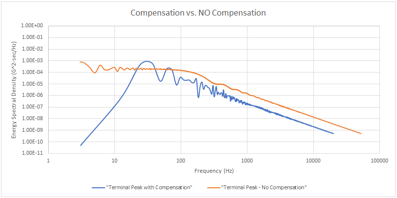
Figure 2.1. Terminal-peak compensation vs. no compensation.
There are methods to help minimize the amount of frequency content generated by the compensation pulses. In the end, however, there is always a trade-off when running a test on a shaker rather than another mechanical shock machine without these limitations.
Some standards are changing the tolerance requirements for pulses, extending them into the time duration with the pre- and post-compensation pulses. The change in tolerance requires lower amplitude pre- and post-compensation pulses, which extends the required duration and increases the test’s overall velocity and displacement. The primary goal of this change is to generate a delta velocity similar to that of a mechanical shock machine.
Conclusion
There are many applications for running classical shock tests on electrodynamic or servo-hydraulic shakers. Shakers offer the convenience of applying positive and negative pulses without re-orienting the product, the repeatability of the waveform shape, and the ability to use common fixturing to other vibration tests. However, engineers must consider the limitations of using a shaker to ensure their test meets the requirements of the test standard.