Sensor Signal Conditioning
June 10, 2022
Back to: Sensors for Vibration Testing
Many measurement systems perform signal conditioning, and vibration control is no exception. The response signals that a sensor outputs are incompatible with the controller hardware, so conditioning is required before processing.
Signal conditioning is performed by the controller or external conditioning equipment. The operation is not the same for all equipment, but several functions are typical for vibration signals.
Signal Conditioning
A sensor’s output—whether voltage, current, or resistance—is often too low for the signal processor. Before a vibration controller processes data, the signal must be amplified. At the same time, the circuit may perform additional functions, including linearization, filtering, and isolation.
Amplification
Amplification increases a signal’s amplitude before digitization. In turn, the controller can more accurately measure the signal and separate the measurement from noise.
Components of a vibration control system can potentially introduce extraneous noise into the measured waveform. Like white noise, there is always some noise in the control loop, and amplification helps minimize its effect.
For example, imagine someone speaking to you in a noisy environment, such as a theme park. Think of how much better you could understand the conversation if the person had a megaphone.
Filtering also serves to reduce noise. Following the example above, if amplification increased the sound level of the conversation, then filtering would remove the unnecessary noise. Instead of the conversation being amplified over chatter, theme music, and rollercoasters, it would be projected into an empty park. At this point, you’re much more likely to receive the message clearly.
Filtering
Conditioning circuits can apply filters to the data stream to reduce noise errors. Filters reject or accept data components based on frequency. They perform some type of operation on a data sequence to yield a new sequence.
Filtering also prevents aliasing, where the digital samples of two sine waves with different frequencies appear identical. Low-pass, high-pass, notching, and bandpass are the most common filtering operations in vibration testing.
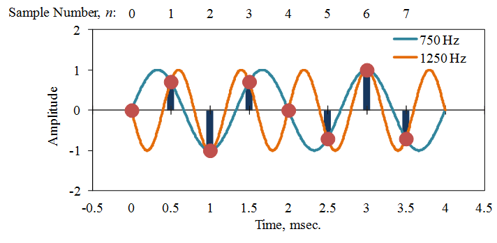
Aliasing sine waveforms.
VR hardware has an anti-alias filter that is always enabled. It includes a combination of analog and digital filtering to prevent higher frequency signals from aliasing back into the waveform and is based on the test sample frequency.
Avoiding Noise Errors
Vibration test engineers want to test their product at a specified amplitude and frequency. In addition to the pure vibration, a controller also measures the inherent noise and harmonics of the shaker system. If the background noise alters the amplitude reading, then the controller will adjust the drive signal. As a result, the closed-loop system will not be controlling the test at the specified parameters.
For example, suppose a controller outputs a sinusoid at 25Hz with an amplitude of 1G. On the product, there is an acceleration of 0.1G at 50Hz and 0.3G at 100Hz, which are both harmonics of the 25Hz resonance. Without a tracking filter, the controller reads 0.4G from the harmonics and 1G acceleration at 25Hz. In sum, the controller measures 1.4G at 25Hz.
The controller seeks a value of 1G at 25Hz, so it decreases the output drive signal. It is now shaking the product at 25Hz with an acceleration lower than 1G, resulting in under-testing. However, the controller still reads a 1G value because it includes the noise and harmonic distortion from other frequencies in the measurement.
For information about removing noise and harmonics from a sine waveform, please visit our article on sine tracking filters.
Additional Conditioning
Linearization
Most sensor outputs are non-linear, meaning their relationship to the physical measurement is not linear. Linearization produces an interpreted signal based on the true output.
Isolation
Electrical isolation protects the digital system and technician from dangerous voltage levels. If a signal is carrying a high-voltage peak, isolation prevents it from reaching the controller.
Electrical isolation also prevents issues due to differences in ground potential. Each component of a vibration testing system has a ground reference in the control circuitry. Issues can arise if there is a potential difference between the controller and sensor’s ground reference. Isolation addresses the difference for an accurate measurement.
Analog-to-Digital Conversion
Signals in a control loop are analog, so they need to be digitized before the controller can process them. Analog-to-digital conversion occurs after amplification, filtering, and other conditioning. Amplification ensures that the signal output meets the range of the analog-to-digital converter (ADC), which improves its measurement.
Controllers perform analog-to-digital conversion and apply digital signal processing to calculate an appropriate output. The goal is to adjust the drive output until the control matches the demand. The digital signal is then converted back to analog before being released as a drive output.
All vibration controllers process signals with digital conversion. The method is faster, easier, and allows for more complex calculations. In fact, all modern signal processing is performed on a digitized signal.
Learn more: Sampling & Reconstruction VRU course.
Conclusion
Signal conditioning prepares data for digital processing. A vibration controller cannot process the output signal as-is, and noise may be obscuring the target data. The sensor type can affect how much processing is necessary, and many different circuits are available for signal processing. However, in all cases, a vibration signal will require some form of signal processing if the controller is to measure it accurately.