Configuring Sensors in VibrationVIEW
June 10, 2022
Back to: Sensors for Vibration Testing
In VibrationVIEW, you must configure the input for each transducer connected to the system. Inputs can be single-ended or differential.
Single-ended and differential signaling are methods of transferring data between components. The difference between them is the reference to a common circuit connection called “ground.” In electronics, ground is not a connection to the physical earth but a reference point to 0 volts.
A single-ended input measures the difference in voltage between the input channel and the reference ground. It amplifies and then outputs the difference.
However, long or poorly shielded cables might pick up electrical noise. Additionally, a combination of earth and reference grounds could lead to a ground loop.
A differential input measures the difference in voltage between two different inputs. It does not reference the common ground. Any noise will be present in both signals, so the difference between them will be eliminated.
The transducer’s calibration datasheet provides a sensitivity value and other necessary information for configuration. Alternatively, some transducers have a transducer electronic data sheet (TEDS) chip that contains sensitivity and other details. When the operator selects the TEDS option, the controller sends a signal to the transducer and automatically retrieves the information.
In VibrationVIEW, the Transducer Database contains a list of transducers for easy input configuration.
Transducer database in VibrationVIEW.
Tips
- If the sensitivity is in mV/G, the accelerometer is likely IEPE, which requires accelerometer power.
- External conditioning is required if the sensitivity is in pC/G. The conditioner will have an additional sensitivity value in units mV/pC.
The new accelerometer sensitivity factors take effect immediately after you select OK.
External Conditioning
Some transducers have power requirements in a unit other than mV/(engineering unit) that are necessary to power the transducer or amplify its signal to a measurable level. Example transducers include constant voltage, differential supplies, charge amplifiers, and current to voltage converters. These transducers require external conditioning to convert their signal to mV/(engineering unit).
Signal conditioners are circuits that measure a signal and subsequently perform functions so that the next device can transmit it. These functions may include amplification, filtering, impendence, etc. External conditioning involves adding equipment between the transducer and input to perform these functions.
Accelerometer power is required for IEPE (integrated electronics piezoelectric) accelerometers. VR systems provide the signal conditioning necessary for IEPE-type transducers internally, eliminating the need for external conditioning. VR hardware inputs and impedances are optimized for IEPE-type transducers when the accelerometer power is applied.
Conditioning for Analog-to-Digital Conversion (ADC)
A signal usually requires conditioning before analog or digital processing. However, VR engineers selected the appropriate ADC for the inputs’ voltage range. If the technician uses external conditioning, the software scales it to the input range set by the ADC’s ability to measure the signal.
Advanced Input Configuration
Additional input configuration options in VibrationVIEW include signal conditioners, capacitor coupling, DC inputs, and low-bias voltage transducers. These are typically associated with specialized transducers. The differential input option is also located in the advanced dialog.
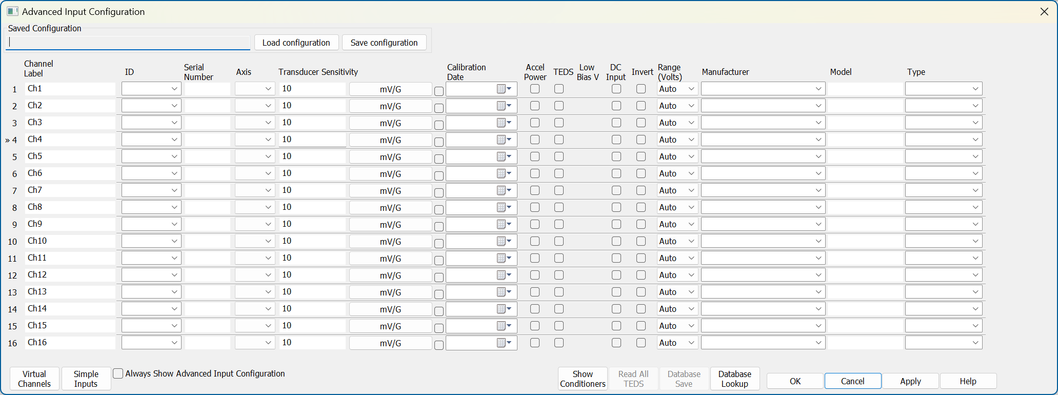
Advanced input configuration in VibrationVIEW.
Capacitor Coupling
Analog and digital circuits have capacitors for various applications. A coupling capacitor is connected between two circuits to block unwanted direct current (DC) power while allowing alternating current (AC) signals to pass through.
The VibrationVIEW option switches the capacitor to the input circuit, resulting in a fixed 3dB corner frequency of 0.16Hz. It is beneficial if the input has a large DC offset that would otherwise overload the inputs.
However, input signals do not usually have a large DC offset, and capacitor coupling should not be selected for a better low-frequency input response. The software removes any DC offset through digital filtering, which provides an adaptive frequency response.
- DC inputs: disables all low-frequency filtering.
- Low-bias voltage transducers: option for IEPE bias voltage less than 9V.
VibrationVIEW System Check
The System Check test mode verifies that a shaker system’s input and output levels and frequencies are correct. The technician enters default frequency and displacement values and then runs the test. There are several troubleshooting options if the shaker does not move, or the input waveform is flat.
After the technician gets an output and input signal, they use a displacement meter to verify that the shaker’s peak-to-peak displacement matches the reference value.