Sensor Installation
June 10, 2022
Back to: Sensors for Vibration Testing
The first step for accurate data acquisition is selecting a transducer with a suitable sensitivity and frequency range. The second is installing the transducer properly.
Problems during vibration testing can arise if the transducer is not mounted to the device under test (DUT) properly, and the data will not be valid. Even the most suitable transducer for a test will provide useless data if incorrectly installed. Most important to consider is the mounting method and the cabling connecting the transducer to the system.
Transducer Mounting
Quality mounting is necessary to obtain accurate data. An improper method can affect the transducer’s frequency response, thereby reducing the validity of the test results. Two things to consider when mounting a transducer are the method and surface preparation.
Methods
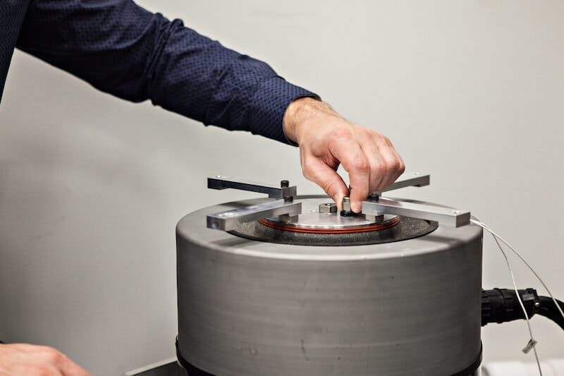
Engineers should select the best mounting method for the transducer. The most convenient option may not necessarily produce satisfactory results. The preferred technique in the industry is the stud mount, where the transducer is directly mounted to a smooth surface. Stud mounting does not affect a high resonant frequency or a broad frequency range.
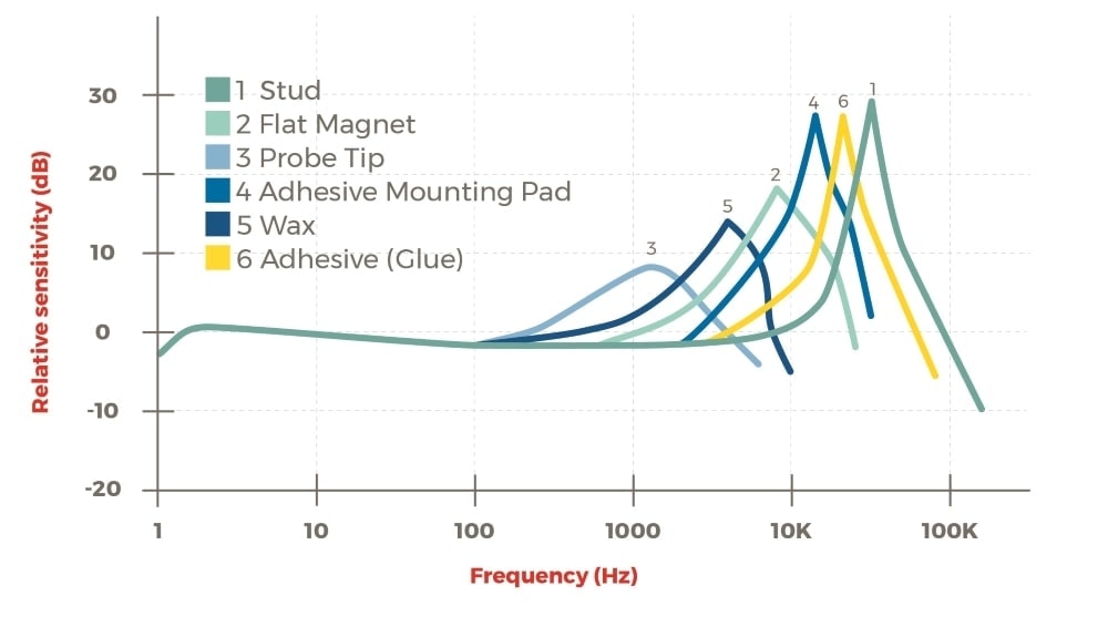
When the stud mount method is unfeasible, adhesives are another option. Cyanoacrylate glue is the best adhesive for accurate results. Engineers sometimes settle for a wax adhesive for convenience, but this can result in poor contact between surfaces, especially under certain temperatures.
Engineers should keep in mind that adding mass to a transducer lowers the sensing system’s resonant frequency, thereby reducing its upper-frequency limit. Soft material can also cause damping.
Surface Preparation
It is also important to properly prepare the surface. The goal should be consistent, uninterrupted contact between surfaces, which can be achieved by applying a thin layer of silicone grease between the transducer and the DUT. Additionally, engineers should avoid uneven or curved surfaces. A clean, flat surface with a thin layer of grease will provide excellent contact between the transducer and the surface.
Transducer Orientation
A common mistake engineers make when mounting is doing so in the wrong orientation. Engineers should confirm the direction that the transducer measures acceleration and mount it in the correct orientation.
For example, an engineer might use a single-axis accelerometer that measures acceleration in the vertical plane and a shaker that vibrates in the horizontal plane (slides back and forth). If they mount the accelerometer as if measuring vertical motion, the data obtained (if any) will be confusing or unusable.
Accelerometer Mounting Tip Sheet
For more tips on mounting accelerometers, please visit our article on the subject.
Cabling
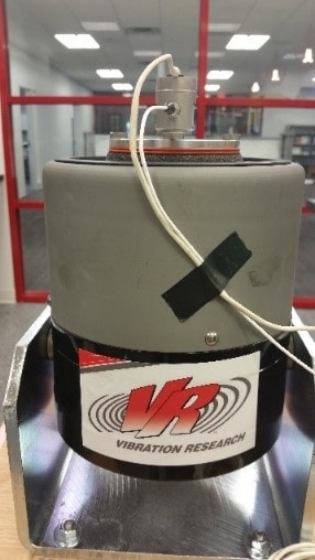
Accelerometer mounted on a shaker.
At a minimum, vibration control systems include a drive output cable between the controller and the amplifier and accelerometer cables between the accelerometer and controller. Cable connection issues can lead to discontinuities in data. Cables must be tightly fastened to the accelerometer, and the cable pin should not be bent or damaged. Joining multiple cables, running them near high voltage wires, and other factors will also affect the signal and lead to issues.
Cables get strewn across the floor, scraped, and kinked, causing the shielding to break down. As it breaks down, the radiant electrical noise of the environment is induced into the cable. The vibration controller measures the environmental noise but cannot control it. Eventually, the ground/shield bond established by the cable will fail, and signals will have no real reference. This failure can cause damage to other components in the system.
Overall, the shorter the cable, the better. The cables in a vibration testing system are one of the most easily damaged components and are common sources of noise problems. In addition to the measurement frequency range, the maximum cable length depends on the type of transducer and cable.
For instance, the distance between charge mode accelerometers and the charge barrel/amplifier needs to be short. These accelerometers output low voltage levels and any noise the cable absorbs from the environment can cause variation in the signal.
For IEPE accelerometers, the wire that carries the voltage supplying power to the accelerometer also carries the signal. The signal has more power and is less subject to variation. As the cable length increases, the inherent impedance and capacitance will change. Depending on the cable type and the output of the IEPE power supply (2mA vs. 5mA), the maximum length can be up to several hundred feet for a well-insulated and low capacitance straight cable.
Vibration Research uses a 1000 Base-T Ethernet connection between the controller and the PC. It allows the technicians to install the controller close to the amplifier and shaker while the operator station can be in a control room up to 300 feet (100m) away. The shorter cables (drive and accelerometer) are more easily maintained, more cost-effective when they need replacing, and remove a lot of confusion when determining which accelerometer is connected to a particular channel.
Learn more: System Noise and Ground Loops VRU course.