VR9500 Automated Calibration Verification Instructions
December 17, 2018
Definitions and Reasons
Automated Calibration Verification
Verify Accelerometer Power and Constant Current Supply
Back to: Preserving VR Hardware Accuracy
Vibration Research recommends an annual calibration verification for vibration controllers and dynamic signal analyzers. In this lesson, learn how to perform an automated verification for the VR9500. Use the following checklist to track and document this procedure.
VR9500 Calibration Verification Instructions
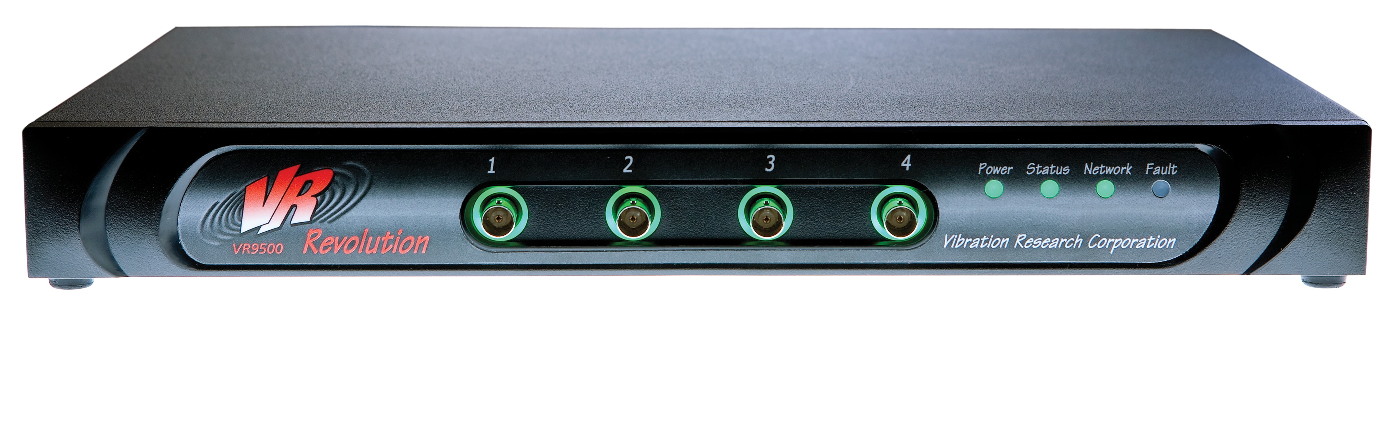
VR9500 I/O Unit.
Equipment/Software
- VR9500 unit that requires calibration verification
- VibrationVIEW Automated Calibration Verification software license
- Keysight IO Libraries Suite software
- (5) BNC (coaxial) cables
- (4) BNC tee connectors
- Dual banana to BNC adapter
- Differential mode tee connector
- Keysight/Agilent/HP 34410A, 34411A, 34461A, 34465A, 34470A, or 3458A digital multimeter (DMM) with valid calibration certificate
NOTE: Equipment is available for purchase through Vibration Research. If using a serial port to USB adapter, we recommend the 232USB9M adapter (not required).
Optional: Measure IEPE Voltage and Current
Before running an automated verification, we recommend measuring IEPE voltage and current to ensure the accuracy of the hardware. To do so, the following equipment is required:
- (3) 50-ohm terminators
- Dual banana to BNC adapter
- 36″ BNC cable
Check IEPE Voltage
- Turn on the accelerometer power for Channels 1 to 4.
- Connect the three 50-ohm terminators to Channels 2, 3, and 4. See Figure 2.1.
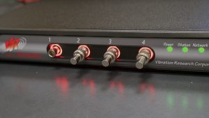
Figure 2.1. 50-ohm terminators connected to Channels 2 to 4.
- Insert the banana adapter into the two holes on the top right of the DMM’s front panel. They should be labeled as Input – HI and LO. Make sure the ground pin is connected to the LO port.
- Connect one end of the BNC cable to the banana adapter (see Figure 2.2.)
- Press the top left button marked VDC.
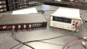
Figure 2.2. Connecting the VR9500 to the DMM to read voltage.
- Connect Ch 1 to the DMM.
- Measure and record voltage (24 Volts DC +/- 2.4 Volts = 21.6Vdc – 26.4Vdc tolerance). Any channel not being measured should have a 50-ohm terminator installed to prevent any leakage across channels.
- Repeat this measurement on each of the remaining inputs. Any channel not being measured should have a 50-ohm terminator installed.
Check IEPE Current
- Connect three 50-ohm terminators to Channels 2, 3, and 4.
- Set up the DMM to read DC amperage by pressing the button labeled DCI in blue.
- Press the Shift button on the lower right, and then press the DC V button on the upper left.
- Rotate the banana adapter down and 180 degrees so it is connected in the bottom two right holes on the DMM’s front panel. The ground pin should be connected to the LO port (see Figure 2.3.)
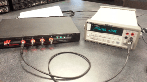
Figure 2.3. Connecting the VR9500 to the DMM to read the current.
- Connect Ch 1 to the DMM.
- Measure and record amperage (3.89mA – 5.43mA tolerance). Any channel not being measured should have a 50-ohm terminator to prevent any leakage across channels.
- Repeat this measurement on each of the remaining inputs. Any channel not being measured should have a 50-ohm terminator installed.
Automated Calibration Instructions
Run Preliminary Verification (1-year Tolerance)
- Connect the VR9500 to a power source.
- Connect the VR9500 to the Windows PC running VibrationVIEW.
- Run VibrationVIEW.
- In the main menu, click Test > Test Type > System Check.
- Run the VR9500 in System Check for 1 hour to allow the temperature to stabilize.
- After the 1-hour warm-up, click Configuration > Verification.
- In the Select Device drop-down list, select the DMM (requires the Keysight communication software).
- In the Select Configuration drop-down list, select Pre-Calibration Check for 9500 at 1-Year Tolerance Levels.
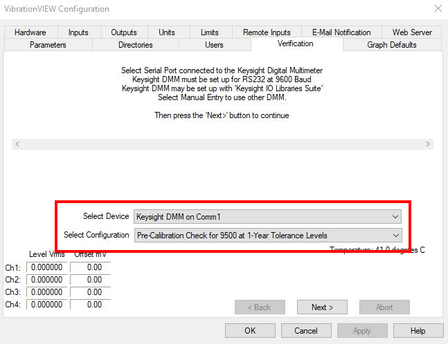
Select Device and Select Configuration drop-down lists in VibrationVIEW.
- Click the Next > button to connect to the DMM.
- A Select User message will appear and require a password. Enter Control as the password and click OK.
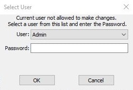
Select User message.
- After communication with the DMM is established, the dialog box will display connection instructions. Verify that the connections are made in accordance with the displayed diagram (for more details, see the lesson Create Differential Cables.) Click Next > to begin verification.
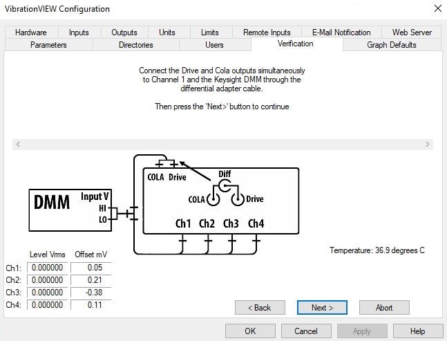
DMM connection instructions in VibrationVIEW.
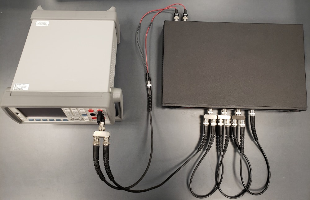
VR95000 unit connected to a DMM.
- A form pre-filled with the DMM details will appear. Fill in the remaining fields with the appropriate values. Click OK. If the procedure fails to meet the 1-year manufacturer specifications, a warning message will appear. Check your cable connections and procedure to confirm the proper steps were followed. If the proper procedure was followed and the result is out of the specifications, then the VR9500 must be recalibrated. Contact Vibration Research for recalibration information.
- If the procedure meets the 1-year manufacturer specifications:
a. Save data as SN-TimeStamp-PreVerify.
b. In the Microsoft Word document, add As received to the first line.
c. Run the full verification.
Run Full Verification (24-hour Tolerance)
- Connect the VR9500 to a power source.
- Connect the VR9500 to the Windows PC running VibrationVIEW.
- Run VibrationVIEW.
- In the main menu, click Test > Test Type > System Check.
- Run the VR9500 in System Check for 1 hour to allow the temperature to stabilize.
- After the 1-hour warm-up, click Configuration > Verification.
- In the Select Device drop-down list, select the DMM.
- In the Select Configuration drop-down list, select the configuration setting Calibration Verification 9500.
- Click Next > to connect to the DMM.
- A Select User message will appear and require a password. Enter Control as the password and click OK.
- After communication with the DMM is established, the dialog box will display connection instructions. Verify that the connections are made in accordance with the displayed diagram. Click Next > to begin verification.
- A form pre-filled with the DMM details will appear. Fill in the remaining fields with the appropriate values. Click OK.
- Upon completion, you will be prompted to save a report file. Enter a file name and click Save.
- If the procedure fails to meet the 24-hour manufacturer specifications, a warning message will appear. Check your cable connections and procedure to confirm the proper steps were followed. If the proper procedure was followed and the result is out of the specifications, then the VR9500 must be recalibrated. Contact Vibration Research for recalibration information.
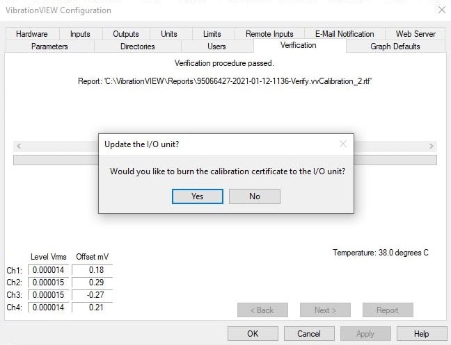
- If the procedure meets the 24-hour manufacturer specifications, then you will also be prompted to generate a calibration certificate. Generating a certificate will reset the calibration due date in the VR9500 and store the reports and data in the non-volatile memory of the VR9500 unit. Click Yes.
- Enter a file name and click Save.
- With VibrationVIEW open and the VR9500 connected, measure the voltage on the aux inputs/outputs connector on the back of the VR9500 between pin 29 (+5V) and pin 30 (GND). If the voltage is less than 4.9 VDC, contact Vibration Research. This value does not affect calibration, but continued equipment reliability may be compromised.
Systems with Multiple VR9500 Units
The Configuration > Verification function verifies the VR9500 configured for Channels 1 to 4. To verify all VR9500 units in a system with multiple VR9500 units, follow steps 18 to 23:
- Select Configuration > Hardware.
- Record the existing box assignment.
- Assign the box to be verified to Channels 1-4 and clear out all other box assignments.
- Run the automated calibration verification procedure for the VR9500 unit.
- Repeat steps 20 and 21 for each VR9500 unit.
- Restore the existing control box assignments.