ObserVR1000 Automated Calibration Verification Instructions
January 12, 2021
Definitions and Reasons
Automated Calibration Verification
Verify Accelerometer Power and Constant Current Supply
Back to: Preserving VR Hardware Accuracy
Vibration Research recommends an annual calibration verification for vibration controllers and dynamic signal analyzers. In this lesson, learn how to perform an automated verification for the ObserVR1000.
Download ObserVR1000 Checklist
ObserVR1000 Calibration Verification Instructions
Equipment/Software
- ObserVR1000 unit that requires calibration verification and a battery charger
- VibrationVIEW Automated Calibration Verification software license
- Keysight IO Libraries Suite software
- Ethernet cable
- Input/output loopback adapter (VR1980) – recommended
- Alternative to VR1980: (17) BNC (coaxial) cables, (16) BNC Tee connectors, and dual banana to BNC adapter
- Keysight/Agilent/HP 34410A, 34411A, 34461A, 34465A, 34470A, or 3458A digital multimeter (DMM) with valid calibration certificate
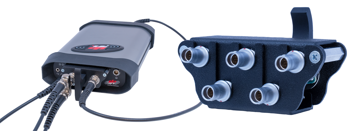
Vibration Research sells a calibration cable kit (VR1980) to simplify the connections required for calibration verification.
Optional: Measure IEPE Voltage and Current
Before running an automated verification, we also recommend measuring IEPE voltage and current to ensure the accuracy of the hardware. To do so, the following equipment is required:
- (15) 50-ohm terminators
- Dual banana to BNC adapter
- 36″ BNC cable
- (5) LEMO to 3 BNC adapter cable
Check IEPE Voltage
- Turn on the accelerometer power for Channels 1 to 16.
- Using the LEMO to 3 BNC adapter cables, connect the fifteen 50-ohm terminators to Channels 2 to 16.
- Insert the banana adapter into the two holes on the top right of the DMM’s front panel. They should be labeled as Input – HI and LO. Make sure the ground pin is connected to the LO port.
- Connect the BNC cable to the banana adapter.
- Press the top left button marked VDC.
- Connect Ch 1 to the DMM.
- Measure and record voltage (25.1V – 30.7V tolerance). Any channel not being measured should have a 50-ohm terminator installed to prevent any leakage across channels.
- Repeat this measurement on each of the remaining inputs. Any channel not being measured should have a 50-ohm terminator installed.
Check IEPE Current
- Using the LEMO to 3 BNC adapter cables, connect the fifteen 50-ohm terminators to Channels 2 to 16.
- Set up the DMM to read DC amperage by pressing the button labeled DCI in blue.
- Press the Shift button on the lower right, and then press the DC V button on the upper left.
- Rotate the banana adapter down and 180 degrees so it is connected in the bottom two right holes on the DMM’s front panel. The ground pin should be connected to the LO port.
- Connect Ch 1 to the DMM.
- Measure and record amperage (2.25mA – 4.50mA tolerance). Any channel not being measured should have a 50-ohm terminator installed to prevent any leakage across channels.
- Repeat this measurement on each of the remaining inputs. Any channel not being measured should have a 50-ohm terminator installed.
Automated Calibration Instructions
Run Full Verification (1-year Tolerance)
- Connect the ObserVR1000 to a power source.
- Connect the ObserVR1000 to the Windows PC running VibrationVIEW with the Ethernet cable.
- Use the input/output loopback adapter to connect the output to the inputs and the DMM.
- Run VibrationVIEW.
- In VibrationVIEW, click Configuration > Hardware. Review the Serial Number field and verify that the ObserVR1000 serial number is displayed.
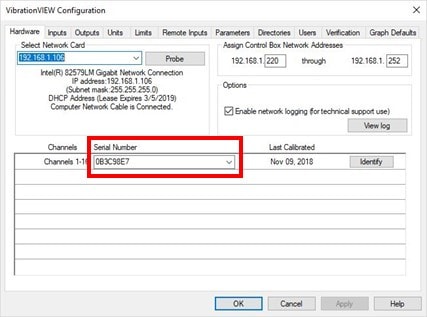
- Click OK.
- In the main menu, click Test > Test Type > System Check.
- Run the ObserVR1000 in System Check for 1 hour to allow the temperature to stabilize.
- After the 1-hour warm-up, click Configuration > Verification.
- In the Select Device drop-down list, select the DMM (requires Keysight communication software).
- In the Select Configuration drop-down list, select the configuration setting Calibration Verification ObserVR1000.
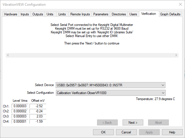
- Click Next > to connect to the DMM.
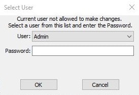
- A Select User message will appear and require a password. Enter Control as the password and click OK.
- The ObserVR1000 will output a small voltage signal and then read it back to verify a connection to the input channels.
a. If the ObserVR1000 is not able to verify all connections, the Next > button will be unavailable. The technician must determine if the error is caused by a faulty connection of the loop-back cable, a faulty wire in the loop-back cable, or a fault with the ObserVR1000.
b. If the ObserVR1000 can verify all connections, a brief fluctuation in the Level VRMS values will occur, and then the Next > button will be available. Click Next >. - A form pre-filled with the DMM details will appear. Fill in the remaining fields with the appropriate values. Click OK.
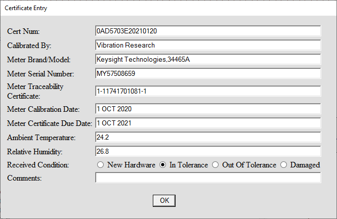
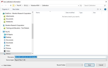
- A calibration verification report searchable by date and serial number is generated when the verification process is complete. The Save calibration information window will appear, regardless if the verification was a success or failure. Select the file location where the report should be saved. Click Save.
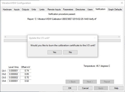
- If the procedure meets the 1-year manufacturer specifications:
a. All recorded measurements fall within the ObserVR1000 accuracy specifications as defined in the ObserVR1000 Calibration Verification Specifications.
b. A message will appear to authorize that a new calibration certificate can be written to the ObserVR1000’s non-volatile memory: “Would you like to burn the calibration certification to the I/O unit?” Click Yes.
c. The Save calibration information window will appear; select the file location where the certificate should be saved. Click Save.
- If the procedure fails to meet the 1-year manufacturer specifications, the following message will appear: “Verification procedure FAILED!!! Some readings are out of the tolerance bands.” If this message appears, then the ObserVR1000 must be recalibrated. Contact Vibration Research for recalibration information.