Phase Response
June 2, 2021
Process Data
Analyze Data
System Identification
Mathematical Foundations
Back to: Fundamentals of Signal Processing
The phase response of a filter transfer function H(ω) is the phase—one of the components of a complex number—of H at the frequency ω.
A transfer function, H(ω), has a magnitude response |H(ω)| and a phase response ϕ(ω) such that H(ω) = |H(ω)| eiϕ(ω).
The only difference between a complex number z and a transfer function H(ω) is z is one complex number whereas H(ω) is an entire function of complex numbers: a complex number for each frequency value ω.
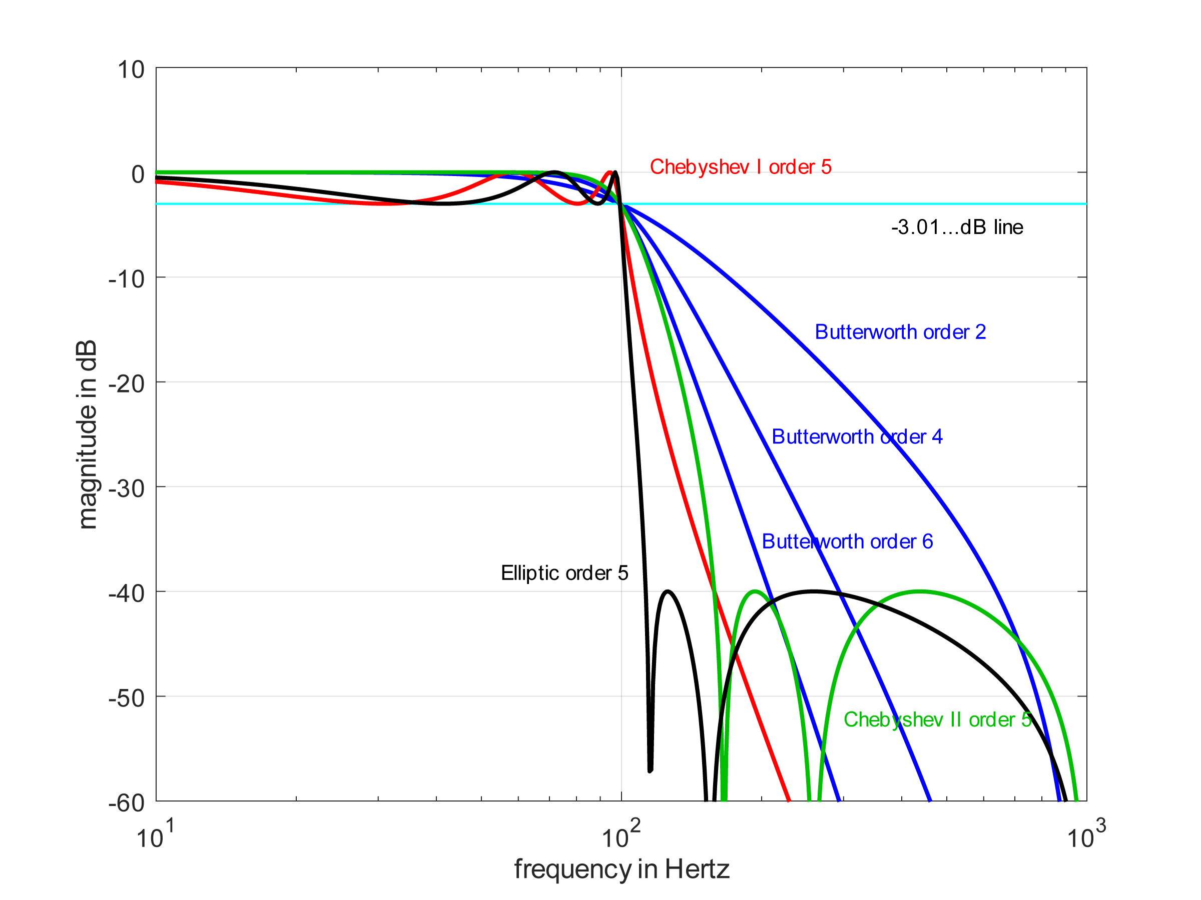
Magnitude in the passband and stopband.
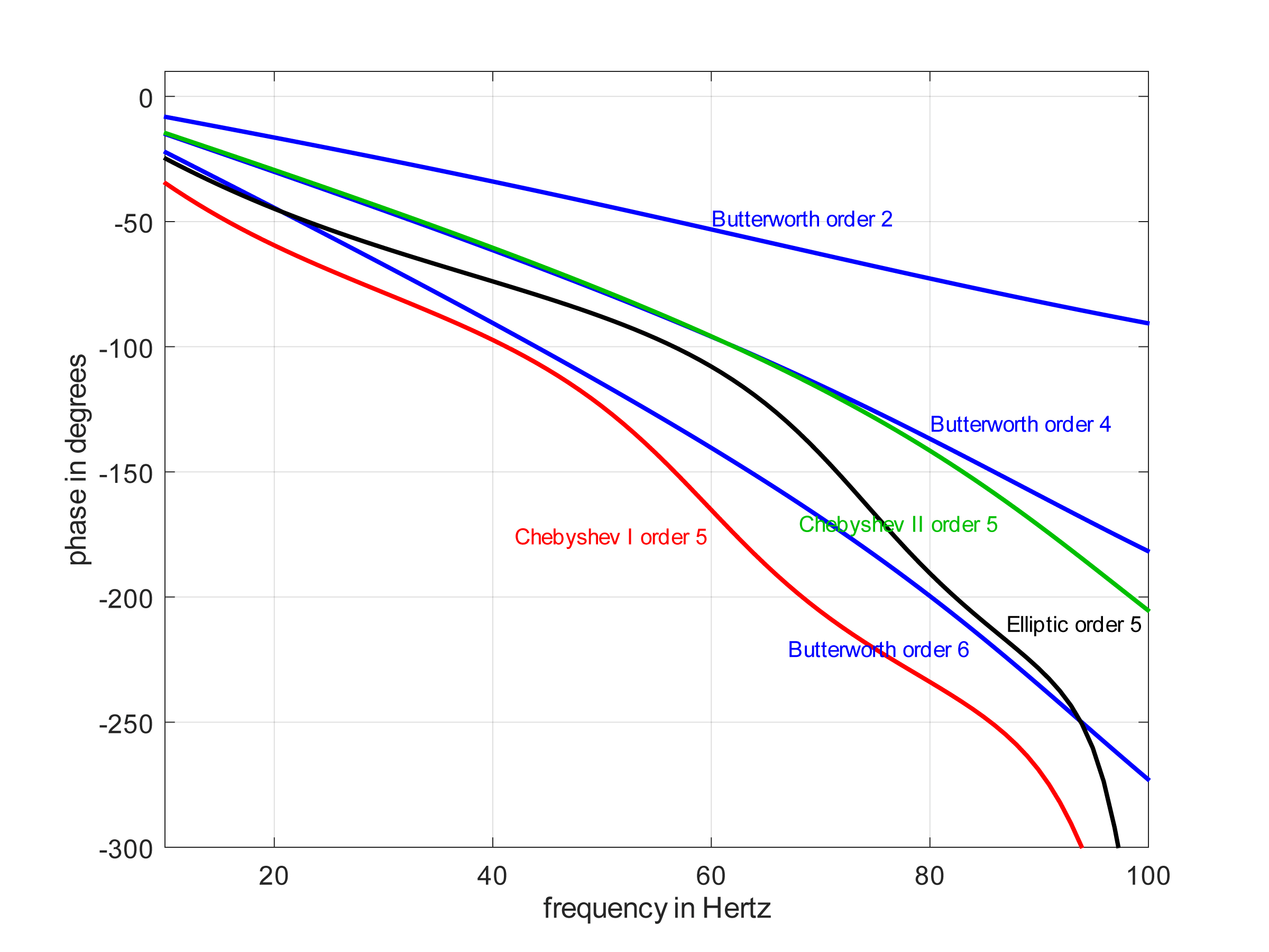
Phase in the passband.
Sign of Phase Response
A phase response ϕ(ω) will always be a real value at every frequency ω. But what if it is positive, negative, or zero? What does the sign of a phase tell us? Here are several tips:
If ϕ(ω)=0, then there is a zero delay through H(ω), and H(ω) is a zero-phase filter. This scenario is only possible when the filter is performing trivial operations such as multiplication by a single constant. Otherwise, it is not physically realizable for real-time signal processing.
If ϕ(ω)<0 for some frequency ω, then there is a delay at that frequency component; the filter output occurs after the input. This scenario is called a causal filter. It is realizable for real-time signal processing. A negative phase is a phase lag.
If ϕ(ω)>0 for some frequency ω, then there is a negative delay at that frequency; the filter output occurs before the input. This scenario is called a non-causal filter. It is not realizable for real-time signal processing but is realizable if the input data is buffered (recorded). As the input is recorded, the filter knows the future input relative to the current time 0. As such, it can yield a future output at the current time 0. A positive phase is a phase lead.
Mathematical Details
|
(1) |
by the convolution theorem |
|
(2) |
by definition of magnitude and phase |
|
(3) |
by definition of X(ω) |
|
(4) |
by definition of Fourier transform of x(t) |
|
(5) |
because eiϕ(ω) is not a function of t |
|
(6) |
because exey=ex+y |
|
(7) |
where u=t-ϕ(ω), so t=u+ϕ(ω) and dt=du |
|
(8) |
by definition of Fourier transform of x(u+a) |
|
(9) |
by change of dummy variable (u to t) |


![\begin{equation*} =|H(\omega)|e^{i\phi(\omega)}FT[x(t)] \end{equation*}](https://vru.vibrationresearch.com/wp-content/ql-cache/quicklatex.com-c2f099b67e4a0064c68fa1500f59d767_l3.png "Rendered by QuickLaTeX.com")


![\begin{equation*} =|H(\omega)|\int\nolimits_{t}x(t)e^{-i\omega[t-\phi(\omega)]}dt \end{equation*}](https://vru.vibrationresearch.com/wp-content/ql-cache/quicklatex.com-c507597cc0a9816fe2fd55a840392136_l3.png "Rendered by QuickLaTeX.com")
![\begin{equation*} =|H(\omega)|\int\nolimits_{u}x[u+\phi(\omega)]e^{-i\omega u}du \end{equation*}](https://vru.vibrationresearch.com/wp-content/ql-cache/quicklatex.com-12c3a8a19181480ea4ee4da11e7072c1_l3.png "Rendered by QuickLaTeX.com")
![\begin{equation*} =|H(\omega)|FT[x(u+\phi(\omega))] \end{equation*}](https://vru.vibrationresearch.com/wp-content/ql-cache/quicklatex.com-347e0be3761a01753a94a3c4e03c617d_l3.png "Rendered by QuickLaTeX.com")
![\begin{equation*} =|H(\omega)|FT[x(t+\phi(\omega))] \end{equation*}](https://vru.vibrationresearch.com/wp-content/ql-cache/quicklatex.com-c5ba4cdd83951636f4172fc408fc7b1e_l3.png "Rendered by QuickLaTeX.com")
The output frequency component Y(ω1) at frequency ω1 is |H(ω1)| multiplied by a version of x(t) that has been delayed by -ϕ(ω1) seconds.
Examples
Let |H(ω)| = 1 and ϕ(ω)=-(ω/2π)2.
If x(t) = sin(2πt), then:
y(t)= |H(ω)|sin[2π(t-ϕ(ω))]
= sin[2π(t-(2π/2π)2)]
= sin[2π(t-1)]
The output is delayed 1 second from the input.
If x(t) = sin(2π2t), then:
y(t) = |H(ω)|sin[2π(t-ϕ(ω))]
= sin[2π(t-(2π2/2π)2)]
= sin[2π(t-4)]
The output is delayed 4 seconds from the input.
Linear Phase
The phase response ϕ(ω) of a transfer function H(ω) is linear if ϕ(ω) = aω, where a is a constant real number.
If the phase ϕ(ω) of a filter response H(ω) is linear, then every sinusoid (pure tone) at any frequency will be delayed by the same amount of time, and this delay will be equal to -a.
For example, if ϕ(ω) =0.05ω and |H(ω)|=1, then:
- x1(t) = sin(2π100t) at the input leads to y1(t)=sin[2π100(t-0.05)] at the output
- x2(t) = sin(2π300t) at the input leads to y2(t)=sin[2π300(t-0.05)] at the output
Both the 100Hz sinusoid and the 300Hz sinusoid will be delayed by 0.05 seconds.
Application
Of the two common types of LTI filters, FIR filters can be easily designed to have a linear phase, and IIR filters are often approximately linear in the passband.