Measure the Controller Noise Floor
February 13, 2020
System Noise in Vibration Control Systems
Noise Troubleshooting
Back to: System Noise & Ground Loops
Measuring the controller noise floor is the first step in determining the source of noise in a vibration testing system.
- Power down the amplifier, blower, hydraulic pumps, and any other auxiliary systems.
- Disconnect the sensors from the controller.
- Remove any products or fixtures from the slip table or head expander.
- Configure the inputs in VibrationVIEW.
- Select Configuration > Inputs.
- Set the Ch1 sensitivity to the sensitivity of the control sensor; the appropriate sensitivity will ensure that all recorded values are comparable and at the same relative level.
- De-select the Accel Power checkbox for the Ch1 input.
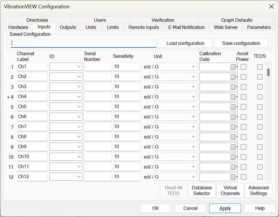
Inputs tab in VibrationVIEW.
- Configure System Check.
- Select Test > Test Type > System Check.
- Select the Edit Test button and set the sample rate to 32,768Hz and FFT analysis lines to 32,768. These settings will give a 0.5Hz resolution out to 16kHz.
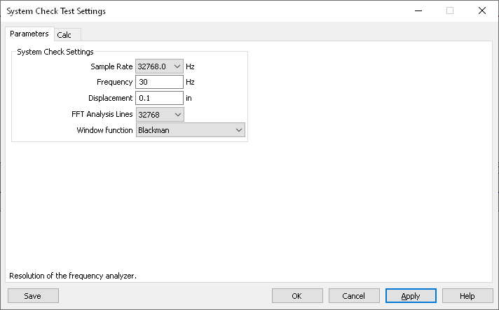
System Check test settings in VibrationVIEW.
- The default graphs in System Check should be an acceleration waveform and acceleration spectrum. If the display does not include one or both graphs, add the graph(s).
- Measure the controller’s base noise floor.
- Terminate the controller inputs by shorting the input pin to the input shell with a 50-75ohm BNC terminator or jumper.
- Verify that the amplifier’s power is off and the gain status is RESET.
- Disconnect the drive cable between the controller and the amplifier.
- After 10 seconds, select the Save Data button and name the file “1 – Controller Noise Floor.”
This data file will serve as a reference for troubleshooting. It is the lowest amount of noise that will always be visible in the system.
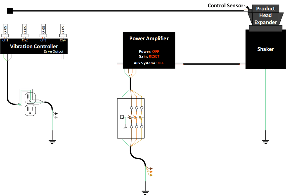
Figure 2.1. Configuration to measure the noise floor.