Ground Loops in Vibration Testing Systems
February 13, 2020
System Noise in Vibration Control Systems
Noise Troubleshooting
Back to: System Noise & Ground Loops
As the previous lesson mentioned, an electronic ground can be a reference to 0 volts (0V). This 0V reference is used as the base measurement for other voltages generated in the testing system. It is the primary reference point and must be appropriately maintained.
Understanding Ground Loops
A ground loop occurs when multiple devices with an earth ground to a building’s electrical power supply circuit are connected via a cable that carries a 0V ground connection. This connection creates multiple paths to ground through multiple devices.
A 0V reference affected by a ground loop is no longer exactly 0V, as an additional voltage is now present. This change can cause errors with the system’s measurements.
Vibration Testing Systems
Vibration testing systems have a complete ground connection through a set of interconnecting cables going from:
- The controller output to the amplifier
- The amplifier to the shaker
- The shaker to the control sensor
- The control sensor to the controller input
In addition to this complete loop of single-point ground references, the controller, amplifier, and shaker have safety ground references to earth ground.
The multiple references to earth ground and the interconnected cabling have a high potential for creating ground loops, especially when the different components require different types of power (120V-Single Phase, 480V-3 Phase, etc.). See Figure 1.3 below.
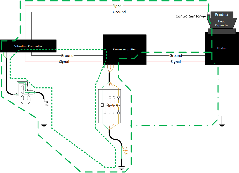
Figure 1.3. Connections and potential ground loops in a vibration control system. The power grounds from all three devices are connected via the electrical power supply circuit.
Resistance and Voltage
Electricity seeks balance; as such, the two wires of a circuit must contain an equal amount of voltage or current. Any imbalance is transmitted to ground.
Different voltages are generated depending on the resistance in the imbalanced wires. According to Ohm’s law, voltage equals current times resistance:
V = I * R
As the resistance increases, the overall voltage increases, even when the current remains the same.
High-resistance wires and circuits will result in a higher voltage signal being carried on the ground side of the cables. In some cases, this voltage difference can cause actual motion on the shaker. In others, the difference may only be measured by the vibration controller.
Detecting Ground Loop Noise
There are two indications that your vibration control system is experiencing ground loop noise:
- The shaker head is moving when the system is powered on, but no test is running.
- The graphs display amplitude bumps at the cycle frequency of the electrical power supply (60Hz in North America, 50Hz in Europe and most of the world).
If you suspect noise is affecting your vibration control system, the following lessons will take you through troubleshooting steps.