VR Controller Set Up
March 16, 2020
Getting Started
Equipment Setup
Software Setup
Navigating the Software
Back to: Getting Started with VibrationVIEW
The VR9500, VR9700, VR10500 and ObserVR1000 can function as a vibration controller with the VibrationVIEW software. Setting up your VR equipment and configuring a test takes just several minutes. If you have any questions, our support team is available to help.
For system settings, troubleshooting, and safety precautions, please refer to the software’s Help file or the User Manual.
VR9500 Vibration Control System
Equipment (Included)
- AC power cable
- Drive cable
- Network (Ethernet) cable
Hardware Overview
The front panel has four BNC input connectors (see Figure 1.)
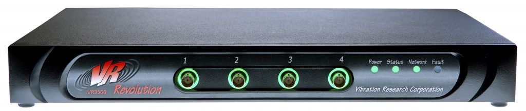
Figure 1. VR9500 front panel.
The rear panel has two BNC output connectors (a DRIVE port and an AUX port) and an Aux I/O DB37 connector (see Figure 2.)
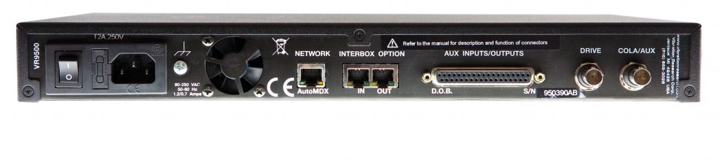
Figure 2. VR9500 back panel.
Setting Up the Hardware
Set up the workstation computer in the conventional configuration with power cables, mouse, keyboard, and monitor.
- Connect the VR9500 network port to the dedicated network card on the computer using the Ethernet cable.
- Connect the power cord to the VR9500. The power input will automatically switch for voltage 90 to 250VAC and 50/60Hz.
- Connect the shaker amplifier to the drive output connector on the rear panel of the VR9500.
- Connect a transducer to Channel 1 on the front panel. Additional transducers can be connected to Channels 2, 3, and 4.
- Power on the VR9500.
VR9700 Vibration Control System
Equipment (Included)
- AC power cable
- Drive cable
- Network (Ethernet) cable
Hardware Overview
The front panel has four BNC input connectors (see Figure 3.)
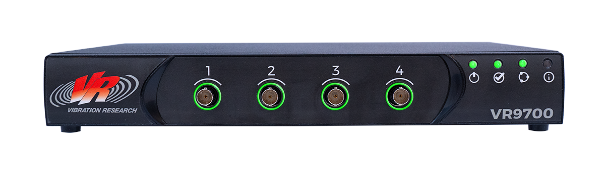
Figure 3. VR9700 front panel.
Setting Up the Hardware
Set up the workstation computer in the conventional configuration with power cables, mouse, keyboard, and monitor.
- Connect the VR9700 network port to the dedicated network card on the computer using the Ethernet cable.
- Connect the power cord to the VR9700. The power input will automatically switch for voltage 100VAC to 240VAC and 50/60Hz. (Note: The VR9700 does not have a power switch.)
- Connect the shaker amplifier to the drive output connector on the rear panel of the VR9700.
- Connect a transducer to Channel 1 on the front panel. Additional transducers can be connected to Channels 2, 3, and 4.
VR10500 Vibration Control System
Equipment (Included)
- AC power cable
- Drive cable
- Network (Ethernet) cable
Hardware Overview
The front panel has 16 BNC input connectors (see Figure 4.)
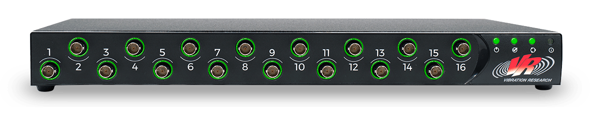
Figure 4. VR10500 front panel.
The rear panel has four BNC output connectors (including a DRIVE port and an AUX port) and an Aux I/O DB37 connector.
Setting Up the Hardware
Set up the workstation computer in the conventional configuration with power cables, mouse, keyboard, and monitor.
- Connect the VR10500 network port to the dedicated network card on the computer using the Ethernet cable.
- Connect the power cord to the VR10500. The power input will automatically switch for voltage 90 to 250 VAC and 50/60Hz.
- Connect the shaker amplifier to the drive output connector on the rear panel of the VR10500.
- Connect a transducer to Channel 1 on the front panel. Additional transducers can be connected to Channels 2 to 16.
- Power on the VR10500.
ObserVR1000®
Equipment (Included)
- ObserVR1000 I/O unit
- IEC C7 AC power cable
- Charger
- Drive cable
- Network (Ethernet) cable
Hardware Overview
The front plate of the ObserVR1000 has an audio input/output, inputs for Channels 1 to 16, and a tachometer input & digital input/output (see Figure 5.)
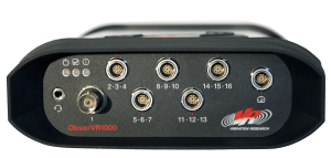
Figure 5. ObserVR1000 front plate.
The backplate has an on/off switch, external A/C adaptor, output, external battery hook-up, SD slot, GPS, USB, and Ethernet.
Watch: ObserVR1000 Hardware Overview
Setting Up the Hardware
Set up the workstation computer in the conventional configuration with power cables, mouse, keyboard, and monitor.
- Connect the ObserVR1000 network port to the dedicated network card in the computer using an Ethernet cable (included).
- Connect the external battery charger (included) to the ObserVR1000 for uninterrupted power.
- Connect the shaker amplifier to the OUT connector on the rear panel of the ObserVR1000.
- Connect a transducer to Channel 1 on the front panel. Additional transducers can be connected to Channels 2 to 16.
- Power on the ObserVR1000.