Sine Test Control Parameters
August 18, 2022
Getting Started
Sine Vibration Testing
Sine Sweep Parameters
Resonance
Sine Resonance Track & Dwell
Running a Sine Test
Back to: Sine Testing
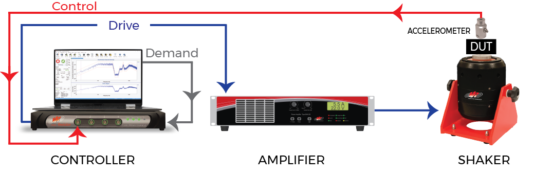
Before we discuss sine test control parameters, let’s cover a basic overview of sine control in a closed-loop vibration testing system:
- The vibration controller generates a sine tone based on user-defined parameters (drive signal), and the power amplifier adjusts the sine tone’s amplitude to the appropriate level
- The shaker runs the sine tone
- The transducer outputs the control signal to the controller
- The controller applies a tracking filter to the signal to isolate the demand frequency and then computes the amplitude of the filtered frequency
- The controller compares the control amplitude to the demand and determines a new amplitude adjustment factor based on the difference between the demand and control
A control loop refers to the physical system and control functions that make adjustments to achieve the desired vibration levels. Adjusting these parameters determines how the control algorithm responds to the output from the shaker table or device under test (DUT).
In the VibrationVIEW Sine test mode, the test engineer can define the control loop parameters under the Parameters tab in the Sine Test Settings dialog box. The parameter values depend on the test definition and setup, although the default values are acceptable in many instances.
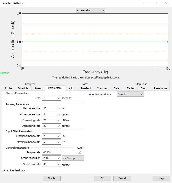
Figure 5.2. Sine Test Settings dialog box in VibrationVIEW.
Startup Parameters
The startup time defines the approximate time it will take for the controller to reach the drive limit output. A startup time of 10 to 20 seconds is recommended as a safety precaution because the operator will have time to abort the test if necessary.
Running Parameters
Response time and Min response time
The Response time and Min (minimum) response time are the primary loop-tuning parameters in the VibrationVIEW Sine test mode. These two response time parameters control how fast the controller adjusts the drive signal’s amplitude to bring the control back in line with the demand, which, in turn, determines the stability of the control.
The controller does not simply adjust the drive sine tone depending on the difference between the control and demand, as it would make the control unstable. Instead, it uses the response time parameters to draw an exponential curve.
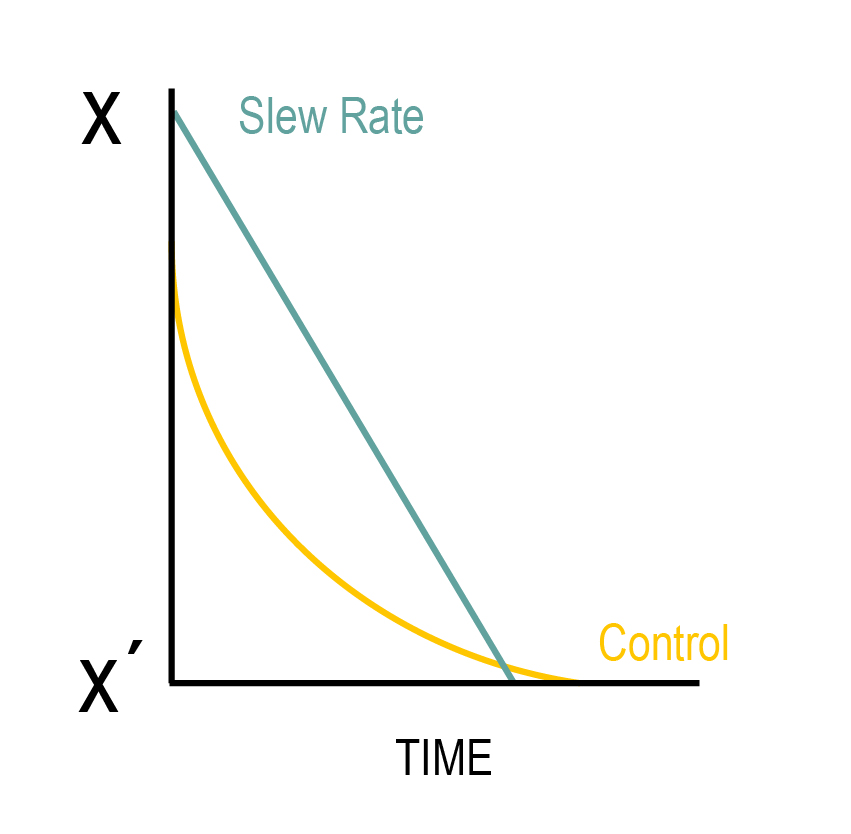
Figure 5.3. A representation of the exponential change of a control signal.
In Figure 5.3, the control signal needs to change from level X to level X’. The signal intercepts level X’ after the user-defined response time.
The controller selects an amplitude adjustment factor for the drive signal to bring to control signal to demand within the user-defined response time. A shorter response time creates a sharper curve and a faster change, but a longer response time increases loop stability.
If the Min response time value (number of cycles at a given frequency) is greater than the Response time value, then the Min response time value determines the loop response.
Increasing and Decreasing rate
The Increasing rate and Decreasing rate are slew rate parameters. They set the output’s minimum and the maximum rate of change.
What is the Slew Rate?
The slew rate is a logarithmic value that determines the test level’s rate of change per second (dB/sec). In Sine, the slew rate is used as a tuning parameter. A faster slew rate allows the voltage to adjust through sharp resonances, and a slower slew rate improves stability.
The slew rate can be entered for the increasing and decreasing output signals. A slower increasing slew rate can be used to sweep through resonances while preventing overshoot as the signal rapidly decreases past the resonance. For example, a slew rate of 20dB/sec allows the signal to increase by 10x in 1 second.
Input Filter Parameters
The Input Filter Parameters determine the bandwidth of the tracking filters.
Adaptive Feedback
The Sine test mode also offers the option to apply adaptive feedback.
What is Adaptive Feedback?
Adaptive feedback permits the system to automatically adjust the control loop parameters. This option allows for tighter control outside a resonance while ensuring stability at sharp resonances.
In the Sine test mode, the Low setting intervenes minimally, while the High setting provides significant intervention at resonance. The Manual settings option offers control of the adaptive algorithm beyond the automatic preset values.
Sine Vibration Testing Software
The VibrationVIEW Sine test mode detects resonances using a swept and/or fixed-frequency sine wave test with control of acceleration, velocity, and displacement. When paired with a VR vibration controller, the user can define the feedback parameters of the system in order to control the actual output or select adaptive feedback for automatic control.
The following video walks us through a modified sine test specification and discusses how to enter it into the VibrationVIEW software.
Tech Talk Video (36:52)
Main Takeaways
- How to enter a sine test specification into the VibrationVIEW software
- How to tune a sine controller
Download the free demo of VibrationVIEW today to set up and design tests before running them on a shaker, view and playback data files, and more. Interested in learning more? Visit the software page.