Q & A: Calibration Verification
May 30, 2019
Back to: Preserving VR Hardware Accuracy
Verifying a Controller When the Accelerometers Are Calibrated
The calibration of all measurement components of a vibration testing and measurement system must be properly verified. Calibration verification ensures that the hardware is accurately measuring signals.
The Vibration Research controllers combine analog and digital circuitry to accurately measure the electrical signals generated by various types of sensors. However, all electronic systems are subject to some form of fatigue and drift due to normal use and VR systems are no exception. While we use only the highest quality components and implement a rigorous testing system to minimize drift, it is impossible to eliminate.
Example of Drift
An extreme example would be hardware experiencing a 5% drift. If an accelerometer was calibrated perfectly at 10mV/G, a 5% drift would be like changing the sensitivity by 5%. As a result, the measurement would be 10.5mV/G. A 0.50 difference may seem small but can result in significant error. For example, the correct measurement for a 50mV signal is 5G, but the post-drift measurement is 4.8G.
As the amplitude increases, this difference will become more severe. At full scale, a 10mV/G accelerometer can measure approximately 500G of acceleration. A 5% drift at this level would result in a measurement of 476.19G, which is almost a 24G error.
The same type of expanding measurement error behavior can occur with VR controllers. It is just as critical to verify a vibration controller as it is an accelerometer. If the measurement of the controller is not verified, any test run with the controller is unreliable.
Does Calibration Verification Only Run in Sine Test Mode? What about Random?
Calibration verification only runs in sine test mode. Here’s why:
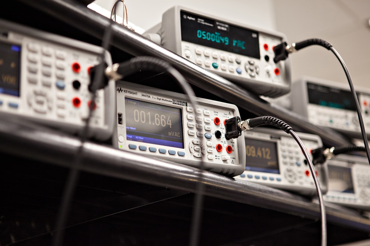
Calibration verification of a hardware unit connects the output directly to all inputs with a simple BNC cable. The hardware and cabling create a linear system to avoid variance in loss or damping across the frequency ranges. The system is also time-invariant because there is no shift in period or duration between the output signal generated and the input signal measured.
Linear Systems and the Superposition Principle
For all linear systems, the superposition principle states that if signal A generates a measurement X, and signal B generates a measurement Y, then signal A+B = measurement X+Y. When the fast Fourier transform (FFT) converts a time-domain signal into the frequency domain, it breaks the signal into a series of narrow bandwidth tones that are spread evenly across the desired frequency. Essentially, these narrow bandwidth tones are sine tones with varying amplitudes. Therefore, in the linear calibration verification system, a random signal is simply an additive set of sine tone signals. Verifying the calibration using a set of sine tones is the same as verifying the calibration using a random signal.
Additionally, the root-mean-square (RMS) calculations for digital multimeter (DMM) measurements of a random waveform will not match the RMS calculations for the controller’s measurement of a random waveform. The DMM measures across a frequency range that will not match the frequency range of a random test performed by a controller. This issue does not exist for sine waveforms, which makes sine test mode the obvious choice for calibration verification.
What Options are Available for Calibration/Calibration Verification of Vibration Research Hardware Units?
Vibration Research Headquarters
Calibration of Vibration Research hardware can only be performed at VR headquarters or at an approved sales and support office.
Laboratory Verification
There are several options for the calibration verification of Vibration Research hardware. The Vibration Research lab offers two levels of calibration verification:
- An ISO/IEC:17025-2005 accredited calibration: the laboratory is accredited by A2LA to meet the requirements of ISO/IEC:17025-2017. Calibration certificates and reports are provided with the stated measurement uncertainty for each measurement taken.
- A NIST traceable calibration certificate: no measurement uncertainty is included in the final report.
Automated Verification
Vibration Research also offers software for automated calibration verification. This method requires either a permanent or annual calibration verification license. The software is already activated if the hardware is part of a current Upgrades & Support Agreement. Additional equipment is required: see the Procedure lesson for details.
In-House Verification
Calibration verification can also be performed with an in-house, customized procedure. Vibration Research recommends modeling any custom procedure after the manufacturer recommendations.
If a hardware unit is no longer generating in-tolerance measured voltages, then the unit will need to be returned to the Vibration Research headquarters for calibration adjustment and any necessary repair. Please contact vrsales@vibrationresearch.com for more information.