Multi-axis Vibration Testing
March 29, 2022
Multi-Axis Testing
Back to: Multi-shaker Control
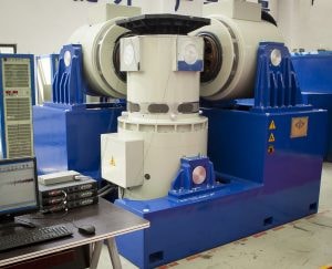
Figure 5. Three-axis vibration shaker.
There are three linear axes of motion in the x-, y-, and z-directions and three rotational axes: pitch, roll, and yaw. A multi-axis test subjects a device under test (DUT) to vibration in two or more axes simultaneously. The test setup includes one vibration controller with multiple outputs or multiple controllers. The output to the shakers can be the same or individual test profiles.
Although it is a more time-consuming process, single-axis testing can capture the effects of vibration at each axis. However, it cannot act out the effect of individual axes’ vibration on each other or the system as a whole. Multi-axis testing can be more rigorous and may more accurately reflect real-world vibration.
There has been a significant discussion about uniaxial versus multi-axis testing in research, academia, and industry. The consensus is that multi-axis testing can be more realistic than subsequent single-axis tests. However, industries are at different stages of implementation and acceptance.
When to Use Multi-Axis Testing
Excitation is typically multi-directional. If the operational environment includes multi-axis loading, the engineer may consider a multi-axis testing method in the lab. As outlined in the introduction, there are several types of multi-axis tests, including:
- Three-axis (multiple-exciter, multiple-axis)
- Four-post
- Six-degrees-of-freedom
Determining when to select a multi-axis test over a single axis will depend on the operational environment and test specifications. According to MIL-STD-810G Method 527:
“As a result of the increased complexity of application of MET [multi-exciter testing] over even multiple application of SDOF single-exciter testing (SET), an analyst after careful review of the available data and specification, will need to provide rationale for selection of the MET method.”
Reasons a laboratory may choose multi-axis testing include:
- Better real-world simulation, particularly with test articles that have a dynamic response
- Shortened test time
- Test articles that exceed single-shaker capabilities
Issues with Multi-Axis Configurations
Multi-axis testing is a promising development, but its configurations have raised several concerns. This test setup requires attention to new details.
Coupling
A multi-axis configuration may require coupling multiple shakers to a table. Ideally, a shaker moving along one axis should transfer its motion to a table without affecting the other axes of motion. When coupling is set up properly, the shaker should move the table along one axis without causing significant motion in the others.
Cross-axis motion occurs when excitation along one axis excites another axis or axes. An example would be a slip table moving side to side when its motion should be forward and back. While engineers cannot eliminate cross-axis motion, proper coupling methods can minimize its impact on the system.
A common coupling method employs hydrostatic bearings, which allow connections to pivot freely and permit the transmission of motion from shaker to table. Sliding bearings are another option. Regardless of the coupling method, the goal is to transmit motion without exciting the other axes, letting the table move as freely as possible when excitation is applied.
Resonances
Resonances are more difficult to control in cross-axis motion because excitation along several axes can potentially excite a resonance along another axis or axes.
The Sound & Vibration article titled “Defining the Global Error of a Multi-Axis Vibration Test” describes the potential for differences in excitation levels during multi-axis testing and includes ways to account for the differences. As the article mentions, engineers must design the reference profiles so that resonances are minimized not just along one axis but several.
Accelerometers
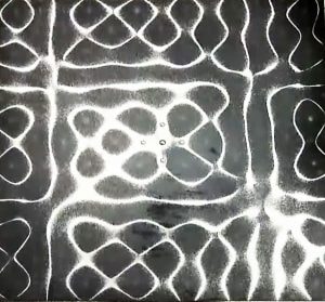
Figure 6. Salt formations on a shaker table.
Transverse sensitivities produce noticeable effects in a multi-axis test because the system is intentionally moving in all directions. Most tables or fixtures aren’t perfectly rigid. For instance, see the salt formations that a shaker table generates in Figure 6. As such, accelerometer location matters.
Accelerometer placement must consider the number of accelerometers and their location. Engineers often use multiple accelerometers to determine motion at a particular degree of freedom. In such cases, the effects of their placement are magnified.
The design of the table’s head expander is also affected by multi-axis configurations, as resonances must be minimized along several axes.