Distortion Introduced by Sampling
July 17, 2019
Sampling
Frequency Domain Consequences of Sampling
Reconstruction Via Interpolation
Quantization noise and over-sampling
Differential Quantization / Delta Modulation
Noise Shaping / Delta-Sigma Modulation
Back to: Sampling & Reconstruction
In general, sampling introduces three types of distortion due to:
- Signal bandwidth
- Quantization
- Digital-to-analog converter (DAC) interpolation
Distortion Due to Signal Bandwidth
In Lesson 2, we learned that perfect reconstruction without distortion is theoretically possible for band-limited signals. However, in the real world, no signal is truly band-limited. If nothing else, there is always thermal noise.
If the sample rate, 𝖥s, is not at least the Nyquist rate, then aliasing occurs (see Figure 1.10.) Typically, engineers prevent aliasing by band-limiting the signal with a low-pass filter (often called an anti-aliasing filter). However, any kind of filtering—no matter how useful—changes the signal and introduces distortion.
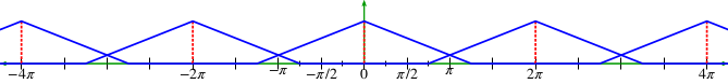
Figure 1.10. Sampling below the Nyquist rate introduces aliasing.
Distortion Due to Quantization
Quantization is the mapping from a continuous waveform to a discrete quantity. Quantization forces continuous signals with an infinite number of possible values to be represented as discrete-value sequences with a finite number of possible values.
For example, a signal in the range of ±1 volt has an infinite number of possible values; however, when sampled by an 8 bit ADC, it is forced to be one of 28 = 256 possible values (see Figure 1.11.) The difference between the ideal value and the discrete value is, by definition, distortion.
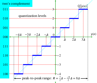
Figure 1.11. Distortion due to quantization.
Distortion due to DAC Interpolation
A digital-to-analog converter (DAC) must convert a sequence of discrete values back to a continuous voltage or current waveform. From a theoretical standpoint, this waveform is ideally a sequence of weighted “infinitely high and infinitely narrow” pulses called Dirac delta functions.
However, real-world systems can’t support infinite voltage levels, so we must settle for more mundane solutions. In practice, engineers often implement simple “sample-and-hold” circuitry or, more generally, Lagrange interpolation (see Figure 1.12.)
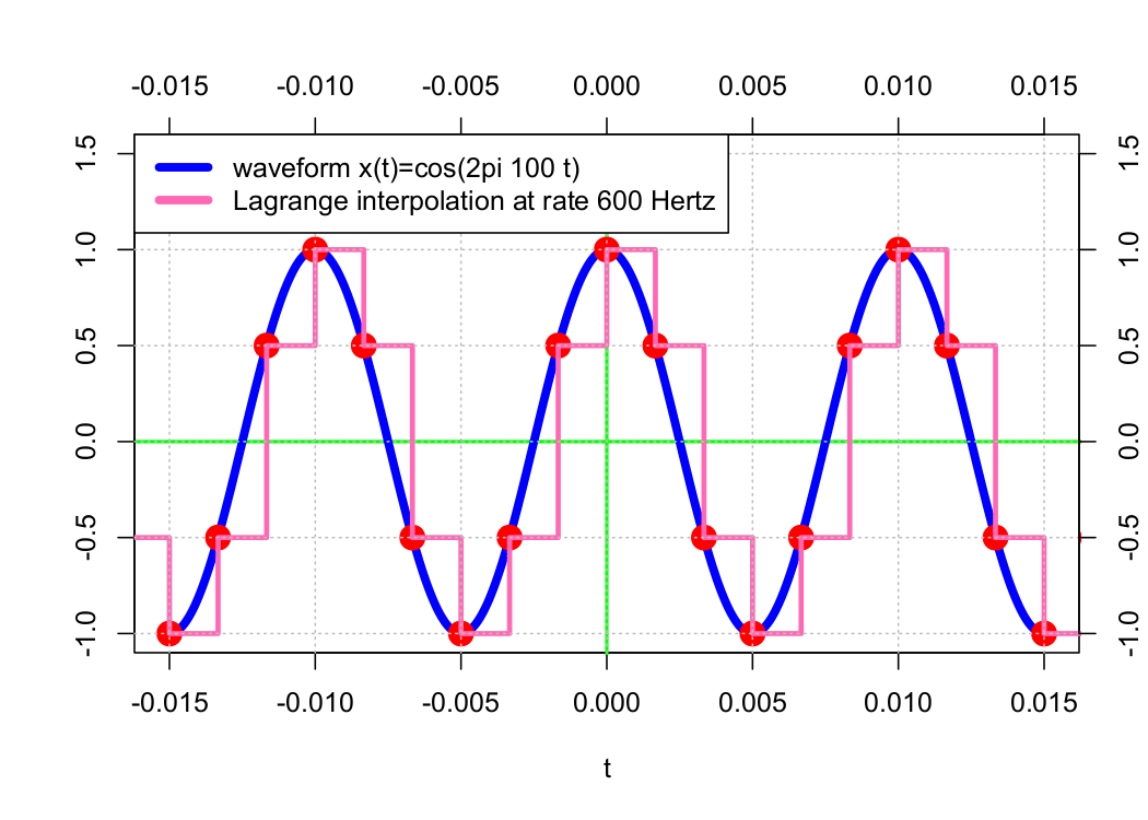
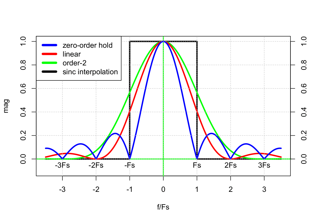
Figure 1.12. Distortion due to DAC interpolation.
Sample-and-hold is simple because it can be implemented with D-flip-flops. However, its operation is equivalent to convolution with a rectangle function. As such, it introduces distortion in both the time and frequency domains.