Aliasing
March 29, 2018
Getting Started
Power Spectral Density
Converting Recorded Data
Statistics & Probabilities
Test Control
Back to: Random Testing
Different sine waves can have identical sample values for a fixed sample rate. Therefore, the frequency value of an FFT result is generally not unique.
Figure 2.18 illustrates this idea with a sample rate of 2,000 hertz (Hz). The digital samples of the two sine waves with different frequencies are identical. For the FFT computation, the higher frequency looks like the lower frequency, thus the origin of the name “aliasing.”
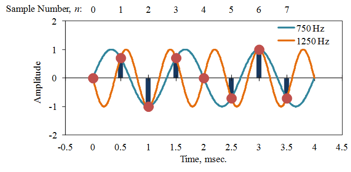
Figure 2.18. Aliasing of digitally sampled sine waves at a sample rate of 2,000Hz.
Aliasing and Low-Pass Filtering
To avoid ambiguity in the FFT, the lowest frequency values are assumed. For a given sample rate (SR), these frequencies lie between 0 and SR/2 = fq. Therefore, all frequencies above the Nyquist frequency must be removed.
Normally, engineers remove the frequencies by passing the signal through an analog low-pass filter before an A/D converter converts the signal to digital samples. A typical low-pass filter begins attenuating the signal at about 80% of the nominal cut-off frequency, so most systems provide good data for frequencies up to f = 0.4 SR.
Note that the aliasing occurs as a mirror image about the Nyquist frequency (and odd number multiples). The frequency fa = fq + df looks the same as the frequency fb = fq – df (with 0 < df < f q ) for a sample rate SR = 2 fq. As does fc = 3 fq – df, fd = 3 fq + df, and so on for all odd-number multiples of fq.