Time-history Versus Wavelet Control
March 15, 2022
Introduction
Control & Analysis
Back to: Shock Response Spectrum (SRS)
A shock response spectrum (SRS) test standard includes a required response spectrum: a plot of the maximum frequency response for a set of single-degree-of-freedom (SDOF) oscillators subjected to the same base excitation. The test engineer synthesizes an SRS pulse in the software to meet the demand. They do so by manipulating a standard synthetic waveform or recorded data with consideration to the DUT, system limits, and test objectives.
Test engineers can synthesize a demand shock waveform using a step-by-step time analysis or a nonlinear dynamic analysis. Time-history control reproduces a given waveform, while wavelet control reproduces a given SRS.
Time-history Control
The goal of time-history control is to reproduce a given waveform. It is similar to classical shock because it requires startup pulses or iterations and memorizes the drive signal to generate the full-level pulses.

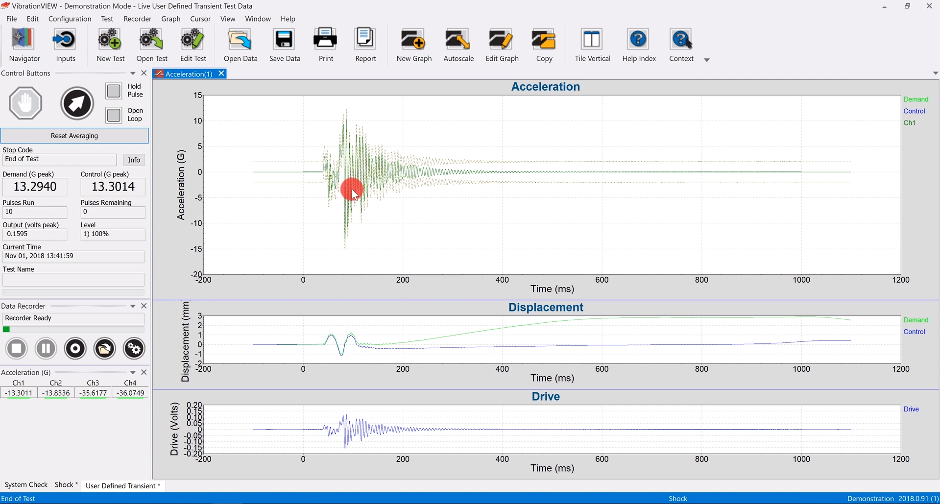
Test data in the VibrationVIEW User Defined Transient software module.
Standard synthetic pulse types include:
- Sine beat, cosine beat, and triple sine beat
- Linear chirp and exponential chirp
- Burst random and enveloped burst random
The equations are pre-defined, so the engineer can create a waveform by setting the appropriate parameter values, including the startup pulse interval, feedback control, and end-of-pulse padding. Alternatively, the engineer can enter a user-defined equation to create a waveform from a recorded event.
Any industry where transient events occur can use time-history waveform control if the goal is to control in the time domain. Uses include earthquake/seismic testing, waveform replication, synthetic pulse generation, modal pulse, and more.
By replicating the time-history files, the test engineer can have better control over recorded events. However, there is no guarantee the resulting SRS is satisfactory. Therefore, engineers more often use wavelet control for SRS test development.
Wavelet Control
The goal of wavelet control is to achieve a given SRS. Wavelet control recreates a test standard’s required response by adjusting the wavelets of a signal. The engineer uses a synthetic waveform or a recorded one as the starting point. The software performs wavelet analysis to separate the waveform into individual functions at set frequencies (i.e., wavelets), and the engineer employs feedback control to fine-tune them. They may boost those at frequencies where the control SRS is below demand and compensate for underperforming SRS frequencies to meet or exceed the criterion. The software combines the adjusted wavelets to make up the control SRS.
Wavelet control can use synthetic waveforms such as linear chirp, exponential chirp, WavSyn, and burst random. Test engineers can also synthesize an SRS from recorded data, as is discussed in the Test Development lesson.
Software Example
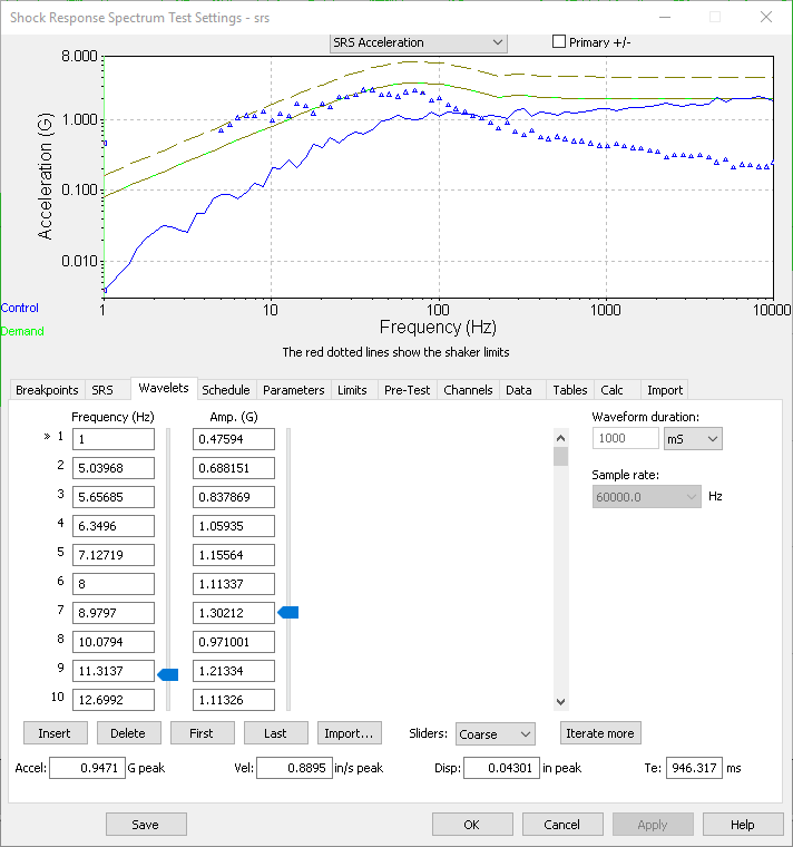
The following is an example of SRS synthesis in the VibrationVIEW software. The green line on the SRS acceleration graph is the demand and the blue one is the control. If the test standard requires that the tolerance “shall meet or exceed the demand,” the minus tolerance must be equal to the demand. If an underlying wavelet is below demand, the test will not count the pulse as valid or enter Run mode at all.
In this case, the engineer must adjust the individual wavelets (indicated on the graph by small triangles) until the waveform meets or exceeds the demand. In the VibrationVIEW software, they can use the “Iterate more” option to automatically adjust the amplitude values to reach the desired SRS profile. The software allows manual fine-tuning of the wavelet frequencies and other parameters, and the automatic iteration improves the amplitude match.

