Basics of Vibration Resonance
June 7, 2023
Basics
Design Stage
Addressing Resonance
Back to: Resonance in Product Development

Figure 1. SDOF system.
To understand the phenomenon of resonance, let us look at a basic mechanical system where a mass is attached to a base by a spring. The spring moves solely in one linear axis, meaning it has a single degree of freedom (DOF) [1].
Although not entirely realistic, most real-life systems behave similarly to a single DOF mass-spring system. We can use it as a foundation for more complex systems.
Figure 1 is an SDOF mass-spring system where m is mass, k is stiffness, c is a damping constant, and x is displacement.
System Resonance
Resonance occurs when a force acts on a system at the same frequency as the system’s natural frequency. When this happens, a system is subjected to large displacements causing significant stresses that lead to damaging results. Test engineers spend time identifying resonances because they are often the root cause of failure due to fatigue.
Every component of a mechanical system has a natural, or resonant, frequency. A single DOF mass-spring system has one, while complex systems often have several in the x, y, and z axes.
Adjusting System Properties
A system’s resonant frequency depends on its stiffness, mass, and damping.
- Stiffness: resistance to deformation determined by material properties and system geometry
- Mass: physical property of a system
- Damping: energy loss in system movement due to resistive forces
By adjusting these properties, an engineer can avoid system damage and its associated time, cost, and safety implications. Which of these properties they alter to mitigate the effects of resonance depends on the driving frequency of the force. We will discuss how to address resonance later in this course.
External Force
Forced vibration generally fits into the category of a base, external, or rotational excitation [2].
- Base: a fixed base of a system vibrates, causing the mass to vibrate
- External: a time-varying force acts upon a system
- Rotational: a component rotates at an angular velocity, causing the mass to vibrate
The simplest excitations are pure harmonic, meaning they can be represented by a single sine or cosine function. A force can also comprise multiple frequency components in the form of random vibration or a transient shock.
System Response
Following initial excitation, a mechanical system’s vibration can be free or forced, meaning it can vibrate free from further excitation or there is continuing excitation. Typically, a mechanical system experiences some type of continuous force, such as the harmonic vibration of a rotating motor.
Damping
Following excitation, a system will try to return to equilibrium. Damping determines how quickly the system reaches this state.
For a harmonic excitation of a single DOF mass-spring system with no damping, the external force applied to the system can be defined by Equation 1…
(1) 
…where F0 is the magnitude of the applied force and ω is the driving frequency.
No real-life system is undamped because there is always some resistive force, such as drag or friction, causing energy loss within the system. Over time, forced, damped systems reach a harmonic, steady-state vibration.
Additional Considerations
Degrees of Freedom
As mentioned earlier, real-world mechanical systems are typically more complex than a single DOF mass-spring system. When operational, most systems experience vibration in multiple degrees of freedom—almost always simultaneously.
Most vibration tests are single DOF systems, where a single-axis shaker applies external excitation to the product in the vertical direction or on a horizontal slip-table. Engineers rotate and re-mount the product to test it in the x, y, and z axes sequentially. To simultaneously simulate real-world field conditions would require a triaxial shaker or 6 DOF shaker, which are expensive and not standard in many industries. You can read more about single-axis testing versus multi-axis testing in the Multi-shaker Control course.
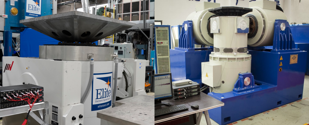
A single-axis shaker (left) and a triaxial shaker (right).
Non-linear Systems
Ideally, the movement of a mass on a spring is directly proportional to the force that the spring exerts. This 1-to-1 relationship represents a linear system. The output response of a linear system is directly proportional to the input force. If you apply multiple forces to the system simultaneously, its response will be the sum of the individual responses to each.
However, this ideal scenario does not perfectly translate to the real world. A system’s natural frequency determines its response, which depends on the mass and stiffness of the spring. Various other factors can affect the system’s linearity, including damping, non-linear characteristics of the spring, and external disturbances.
Most manufacturers design vibration-testing shaker machines to be linear or operate within a linear range. Electrodynamic shakers typically have linear characteristics, and engineers assume linearity when running them. However, engineers must consider that real-world systems have practical limitations and non-idealities that may introduce non-linear behavior.