Accelerometers
June 10, 2022
Back to: Sensors for Vibration Testing
The accelerometer is the most common transducer in the vibration testing industry. Accelerometers tend to be small instruments with rigid construction, allowing functionality in severe environments. They are effective over a range of frequencies (from <1Hz up to 30kHz) and have a high dynamic range, which helps test engineers identify large product resonances. The main disadvantage is its limitations at low frequencies.
Piezoelectric Accelerometers
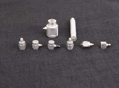
Examples of accelerometer types.
Accelerometers are available in many competing models with varied specifications. Piezoelectric (PE) accelerometers are a popular choice for vibration testing because they are well suited for both vibration and shock tests and are available in many sensitivities, sizes, and weights.
Compared to other accelerometers, the functionality of PE accelerometers is superior at high frequencies (<3Hz to 30kHz) and temperatures (up to 500°F/260°C). Many vibration tests require high-frequency testing because resonance often occurs at these levels.
Accelerometer Technologies
PE accelerometers make use of crystals with piezoelectric effect properties. The applied force of the acceleration puts stress on the crystal, which creates an electrical charge. The sensor then relays the output signal to the vibration controller. Other sensor technologies include:
A piezoresistive (PR) accelerometer contains a mass attached to a variable resistor. When the mass moves, the resistance changes; consequently, the current also changes. PR accelerometers are useful when sudden or extreme vibration is likely to occur.
A capacitive accelerometer functions well at low frequencies. A mass is attached to one plate of a capacitor, and the movement of the plate changes the capacitance.
A micro-electro-mechanical system (MEMS) accelerometer contains a microscopic mechanical structure that can measure frequencies as low as 0Hz. Its high-sensitivity output is ideal for critical measurements.
Integrated Electronics Piezo-Electric (IEPE) Technology
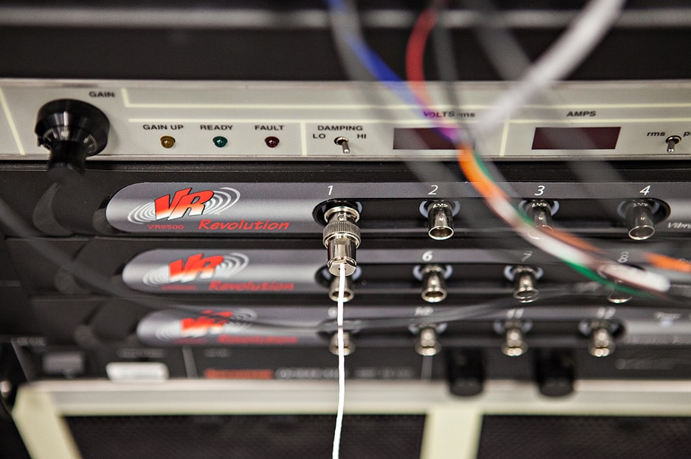
Input connection at channel 1 on a VR9500 controller.
An accelerometer will not read force values if it is not connected to a power source.
An IEPE accelerometer has internal electronics that work with a constant current supply. The wire that carries the voltage supplying power to an IEPE accelerometer also carries the signal. In turn, the signal has more power and is less subject to variation.
IEPE technology complies with a standard, and most IEPE sensors work at a constant current of 2 to 20mA. For example, the BNC input of the VR10500 vibration controller provides a constant current of 4.4mA at up to 26VDC when enabled.
If the current is unable to drive the cable capacitance, the result can be signal noise or distortion. A higher constant current extends the acceptable range of the IEPE sensor’s cable length.
The internal electronics of an IEPE accelerometer boost the output signal and offer high noise immunity due to their low output impedance. An IEPE accelerometer powered by a constant current provides a clean signal and removes many of the noise sources that are common with other types of accelerometers.
Charge Mode Accelerometers
Charge mode accelerometers do not have internal electronics and require a low-noise cable and input charge amplifier. However, they are ideal for high-temperature/high-radiation environments where integral electronics do not function well or at all. (IEPE accelerometers have a maximum operating temperature of about 325°F/163°C.) Charge mode accelerometers and others without integrated electronics require external conditioning.
For most test environments, Vibration Research recommends an IEPE accelerometer with TEDS. IEPE accelerometers do not require specific low-noise cables, charge amplifiers, or other special conditioners. Trade names for IEPE include ICP® (PCB) and ISOTRON® (Endevco).