Live Monitoring During Shaker Testing
December 30, 2025
Measuring Field Environments
Test Monitoring in the Lab
Back to: Recording & Implementing Vibration Test Data
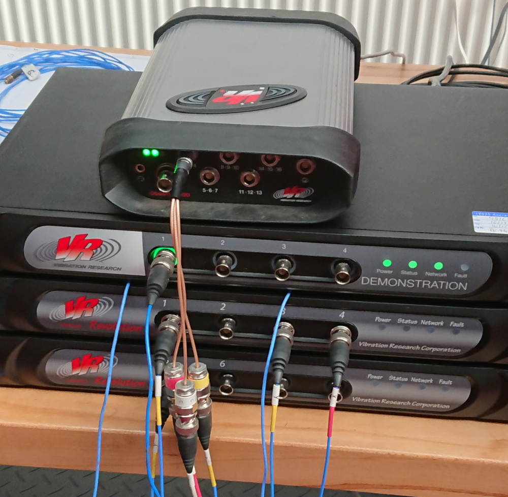
An indepdent verification hardware setup.
Live vibration test monitoring uses an independent data acquisition (DAQ) system to stream data in real time during a test. Broadly, it offers an immediate review of system behavior. An independent DAQ complements the controller’s feedback loop with data while offering verification channel(s) separate from the controller.
Live monitoring does not replace post-process analysis. Post-process analysis improves confidence in testing, while live monitoring can add an additional layer of reassurance. Many labs rely on both to validate their test program and safeguard equipment.
Purpose of Live Vibration Test Monitoring
Broadly, engineers use live vibration test monitoring for test safety, independent verification, and failure detection.
Test Safety
Engineers should reduce the risk of unexpected failures with standard practices such as equipment maintenance, proper parameter selection, and accurate test profile development.
For some labs, test monitoring is a fail-safe measure in addition to these actions. An independent DAQ system and live analysis can point to developing issues such as fixture resonance, overloading, or controller instability.
Vibration controllers can notch or abort a test at defined thresholds, but some laboratories require additional assurance, particularly when handling expensive equipment. Live trends help engineers spot early indicators of failure and stop the test at the most informative moment rather than the most damaging one.
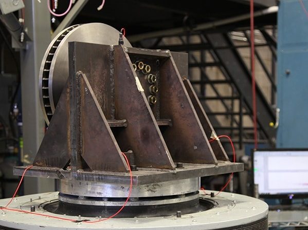
Example of a fixture design on a shaker table.
Independent Verification
Recording data separately from the vibration controller allows engineers to verify the controller’s performance. In industries such as aerospace, the margin for error is minuscule, and independent data recordings provide confidence in test results. Some analyses, such as sine data reduction, require independent verification.
Resources for Independent Verification
Live Monitoring vs. Controller Feedback
Real-time data acquisition requires hardware capable of continuously streaming sensor signals. RecorderVIEW in the VibrationVIEW control software provides real-time acquisition within the control system; however, independent monitoring requires a separate DAQ system, including sensors and sampling hardware.
Independent monitoring differs from controller feedback in purpose and processing. Controller channels drive a feedback loop; the controller processes response signals from the test and adjusts the output signal in reference to the demand. Independent channels do not affect test control. This separation allows engineers to observe resonances, local modes, or structural responses that control channels are not positioned to detect.
Alternatively, engineers can mount analysis sensors at the same location as the control sensors for validation. For a near 1-to-1 comparison between control and analysis channels, matching sensor type and sensitivity is recommended. If using different sensors for independent monitoring, engineers should account for bandwidth, noise floor, and sensitivity during analysis.
Viewing Live Data
Live data streams can be viewed as time waveforms, frequency-domain plots, or trending data. In the Live Analyzer feature, engineers can access ObserVIEW tools, such as the PSD, transfer functions, and user-defined math traces. Math traces are particularly useful for trend detection; engineers can stream calculations such as RMS, ratios, absolute values, or moving averages to monitor stability or identify early signs of failure.
Detecting DUT Failures in Real Time
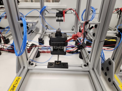
Example of DUT monitoring during a vibration test.
Equally important to the proper functioning of shaker and fixture is tracking the health and performance of the device under test (DUT).
Detecting DUT failures in real time is often the primary goal for vibration testing, particularly for electronics. With live monitoring of critical signals on the DUT, engineers can detect intermittent faults, degradation, or early signs of failure.
Intermittent Failures
Many DUT failures under vibration are intermittent and may not appear during a post-test inspection. After a recall, they appear in the warranty as no trouble found (NTF).
Live monitoring of electrical signals, mechanical responses (strain, force, pressure, temperature, acceleration, etc.), or other functional outputs helps engineers identify intermittent failures in real time, providing insight for design improvements.
Further, engineers need to know when a failure mode begins to manifest during a test. An early failure may indicate a quality problem, whereas a failure later in the test may indicate a material weakness or wear-out phenomenon.
Test Profile Correlation
Intermittent input/output dropouts or logic errors may only appear in a dynamic environment. In addition to monitoring the DUT, the test profile must be correlated to field levels and durations to accurately reproduce real failure modes during testing.
For example, a circuit board may experience a solder joint crack at a specific vibration amplitude, causing intermittent communication errors in real time. These failures could otherwise be easily missed if relying solely on a post-test visual inspection.
A circuit board mounted to a shaker head for vibration testing.
Early Fault Detection
The goal of early fault detection in live monitoring is timely recognition of shifts that signal mechanical or structural change.
Drift
Slow, persistent changes in amplitude or frequency can indicate loosening hardware, softening mounts, or evolving boundary conditions. In Live Analyzer, engineers can track math traces such as RMS or peak to watch for gradual trends.
Sudden Deviations
Abrupt changes in a signal such as unexpected peaks, step changes, or a shift in a dominant frequency usually point to a mechanical change. Labs can assign thresholds to key metrics so that they can pause the test if a response channel departs from its expected range.
Behavior Patterns
Certain patterns tend to appear shortly before a product fails under vibration, such as:
- Resonance peak shift
- Cyclic amplitude changes
- Repeated short-duration spikes
Live Analyzer’s trend views help reveal repeating patterns over a test duration, giving the engineer time to stop the test before reaching a catastrophic state.
Aligning Monitoring to DFMEA
Engineers should align test monitoring with a design failure mode and effects analysis (DFMEA). Any potential vibration failure mode identified in a DFMEA should have a corresponding means to monitor, flag, and identify the failure (or imminent failure) during testing.
Each monitored signal should align with the DFMEA so that any potential failure mode with vibration as a contributing factor can be detected as it begins to manifest, rather than waiting to perform a static post-test functional evaluation.
The vibration test is the “detection mode” of the DFMEA. For electronics, this mode might be in the form of intermittent low voltage communication signals, loss of current, voltage levels amiss, false actuator responses, etc.