Sine in the Frequency Domain
March 29, 2018
Getting Started
Sine Vibration Testing
Sine Sweep Parameters
Resonance
Sine Resonance Track & Dwell
Running a Sine Test
Back to: Sine Testing
Until now, we have discussed sine waves as a function of time and viewed acceleration, velocity, and displacement graphs over time. However, engineers usually analyze sine vibration in the frequency domain. Patterns that are unclear over time are often apparent as a function of frequency.
As data recorders acquire all vibration signals in the time domain, a waveform must be transformed to analyze the data in the frequency domain. For continuous data, engineers use the Fourier transform to do so. In this domain, engineers are most interested in peak acceleration over frequency. The peak values indicate a resonance, an issue with the system, or product failure.
Example
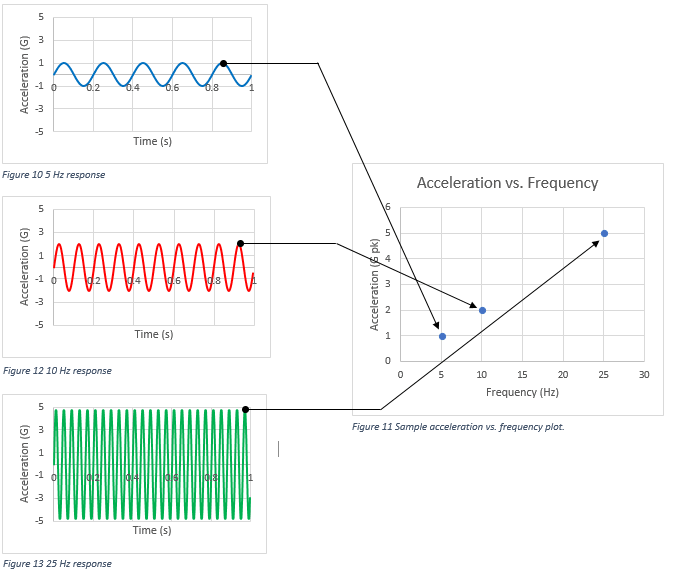
Suppose we test a product with 5 hertz (Hz) vibration at 1G, 10Hz vibration at 2G, and a 25Hz vibration at 5G. The three graphs in Figure 2.3 display the product’s response for each test. To view the product response in the frequency domain, we would plot the peak acceleration of the response versus the frequency range for each test.

Figure 2.3. A sample acceleration vs. frequency plot.
